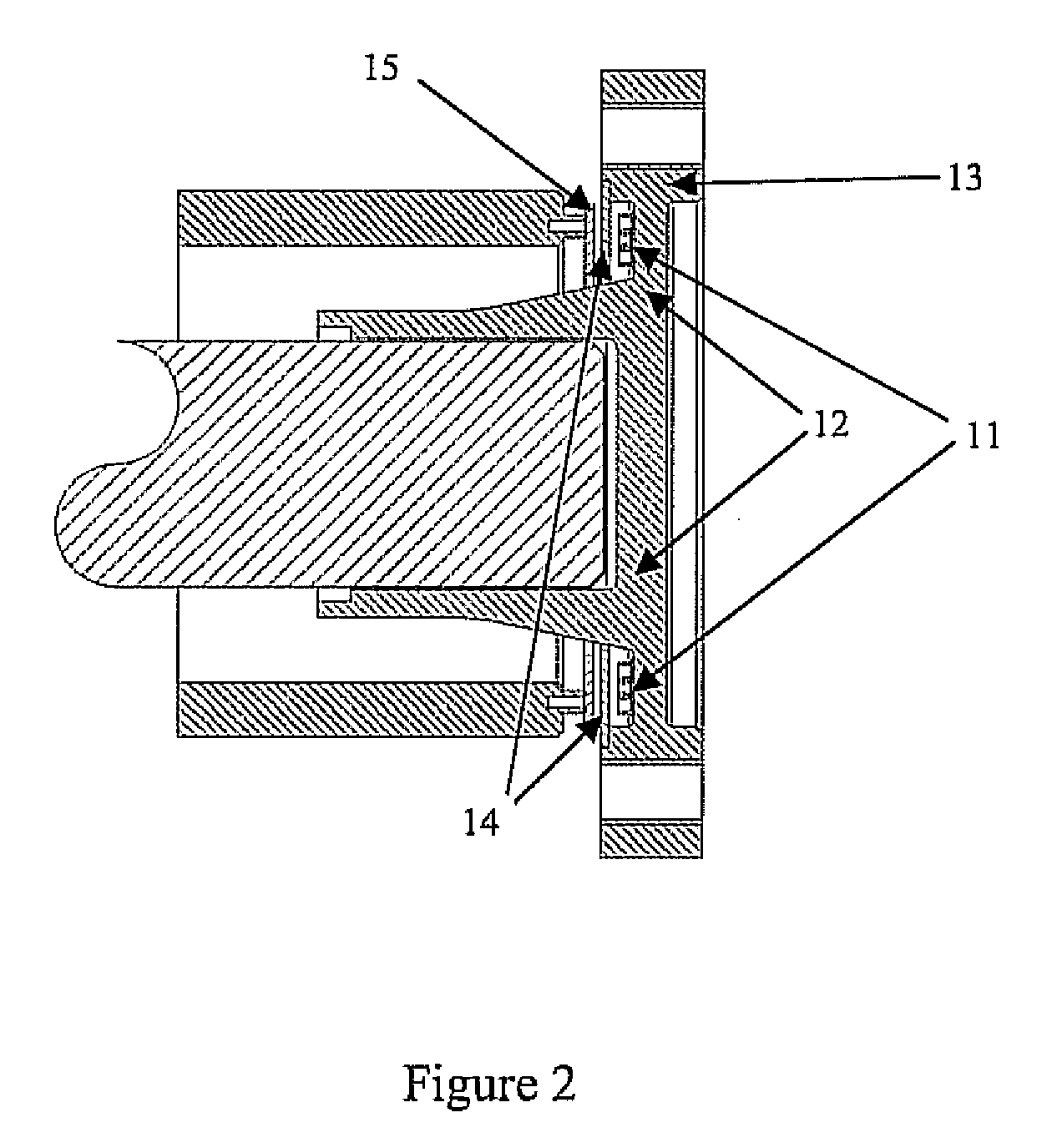
[0022]The present invention derives from the recognition that the principal components of shear strain arising in a disc coupling component in a drive
train are analogous to the strain field developed on the surface of the shaft in torsion, i.e. the principal strains are equal and opposite, tensile and compressive, and oriented at + / −45° to the circumferential direction in the disc component. As a result the greater space available on the disc coupling components, such as the flexplate which is used to connect a crankshaft to a
torque converter in a typical powertrain with an
automatic transmission, the web of a flanged coupling located, for example, between the gearbox output and the prop shaft, can be used to
mount a strain sensor which, due to size constraints, cannot be located directly on the shaft. This has the
advantage of requiring little or no change to the leading dimensions of major components whilst enabling monitoring of the full torque transmitted between those components.
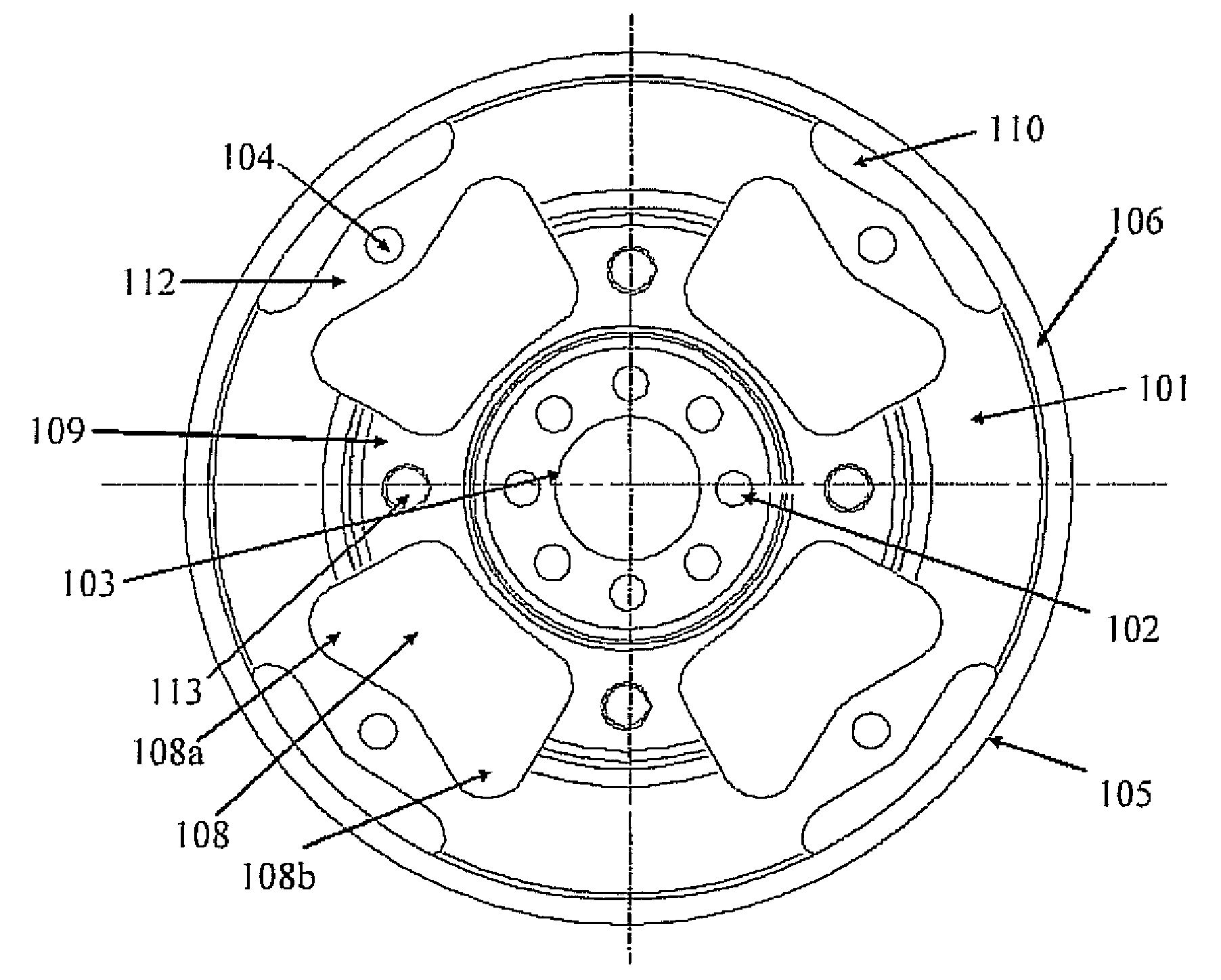
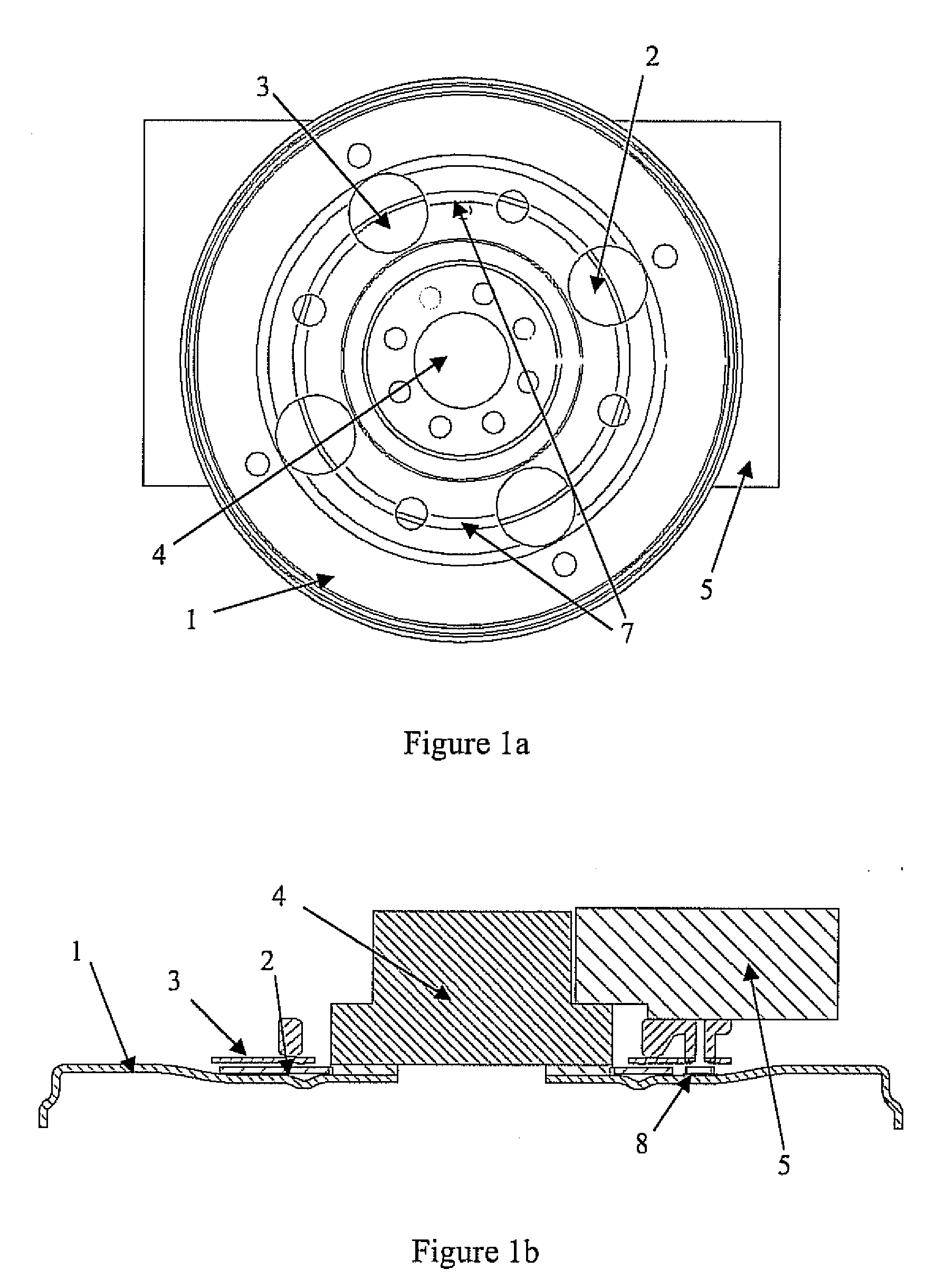
[0024]The sensor is preferably located on a web portion of disc coupling component through which torque between the input and output is transmitted. This web portion may be suitably sized and shaped to concentrate the torsional (shear) strain and hence improve the resolution and accuracy of measurement.
[0026]Such a drive
coupling system has the
advantage that locating of the or each sensor on the local
neutral axis of the disc coupling component minimises superimposed bending strains due to couples acting out-of-plane on the coupling component.
[0027]Preferably, a plurality of circumferentially extending slots are formed in the disc coupling component between each fastening hole and the outer edge of the disc coupling component. The ligaments, formed between these circumferentially extending slots and the adjacent apertures, are essentially flexures which absorb to a significant extent the deflection due to unwanted axial loading and out-of-plane bending and adjust the axial compliance of the coupling component, which thereby increases the measuring accuracy of the sensor.
[0028]Several techniques are involved in providing accurate measurement of torque and rejection of unwanted signals, while maintaining the original design axial compliance, and non contacting sensing capability:1) The distribution of holes on the drive coupling plate, designed to achieve a certain level of axial compliance, is modified so as to generate a small number (typically 3 or 4) of webs to concentrate the shear strain.2) The
active surface of the measuring sensors are placed on the local
neutral axis of the drive coupling plate, thereby minimising superimposed bending strains due to couples acting out-of-plane on the drive coupling plate.3) The measurement sensor or sensors are placed symmetrically on the web(s) so as to minimise strains due to twisting—again due to couples acting out-of-plane on the drive coupling plate.4) Decoupling slots are introduced between the
torque converter fastening holes and the
starter ring in order to create relatively compliant flexures which absorb, to a significant extent, the deflections due to axial loading and out-of-plane couples bending and adjust the axial compliance.5) The thickness of the drive coupling plate may be increased, and the web widths reduced, in order to reduce bending strains (maximised at the surface) while maintaining the desired shear strain (distributed through the thickness) and to physically separate these strain components and to adjust the axial compliance.6) The flatness of the drive coupling plate is improved to minimise strains due to clamping the drive coupling plate to the crankshaft
flange.7) the thickness tolerance is reduced to minimise production variation in the sensitivity of the drive coupling plate which is now essentially a
transducer body.8) The material is re-specified to ensure a sufficiently high elastic limit so the sensor performance is linear and does not exhibit
hysteresis.9) The torque transducers employed are
surface acoustic wave (SAW) devices, which communicate in a non contacting manner (not requiring slip rings) and not requiring active electronic components on the drive coupling plate (no separate power supply). Preferably, three or four through apertures are provided which correspondingly form three or four radial webs. In a particularly preferred embodiment, the through-apertures and fastening holes are equi-spaced on a common pcd.
[0030]The or each sensor is preferably symmetrically located on its associated web, in particular on the radial centre line thereof. In this way, non-symmetrical effects, such as strains due to twisting resulting from couples acting
out of plane on the coupling component are her minimised. The webs are also preferably narrow so as to further decouple sensor output from deflections caused by unwanted forces and moments.

