Acoustic imaging probe incorporating photoacoustic excitation

a technology of photoacoustic excitation and imaging probe, which is applied in the field of imaging probe incorporating photoacoustic excitation, can solve the problems of complex use and manufacture of systems that use this process, generating erroneous range data, and not readily useful for applications

Inactive Publication Date: 2009-01-22
ARNOLD STEPHEN C
View PDF2 Cites 56 Cited by
  • Summary
  • Abstract
  • Description
  • Claims
  • Application Information

AI Technical Summary

Problems solved by technology

The systems that use this process are complicated to use and manufacture.
These systems are not readily useful for applications such as cancer detection due to the requirements for the size of the device required to detect this acoustic chirp, and the processing power required to convert the detected signals into an image.
The issue with this approach is that the signal is restricted to a string of pulses that can be clearly identified so that all ambiguity of correlation can be removed.
Moreover, spurious reflections, even multiple reflections can generate erroneous range data.
Magnetic resonance scanning, ultrasounds, and soft x-ray scans are 3 tools currently used to detect breast cancers, all of which are limited in their usefulness.
Magnetic resonance images are expensive to create.
Many general practitioners do not have direct access to these machines nor do they possess the specialized training necessary to interpret the resulting images, so there is an inefficiency in the implementation of MRI systems.
X-rays have radiation issues, especially for women in child bearing years.
With higher amounts of energy used to excite the blood cells, it may be possible to get the blood cells to emit waves at a higher frequency spectral band, but this may be damaging to the blood cells and surrounding tissues.

Method used


Image

  • Acoustic imaging probe incorporating photoacoustic excitation
  • Acoustic imaging probe incorporating photoacoustic excitation
  • Acoustic imaging probe incorporating photoacoustic excitation

Examples


Embodiment Construction

[0040]In describing the present invention a variety of terms are used in the description. Standard terminology is widely used in the optics and photonic arts. For example, one may refer to Modem Optical Engineering, Warren J. Smith, the disclosure of which is incorporated herein by reference for its general teachings in optical engineering and analogous acoustic engineering.

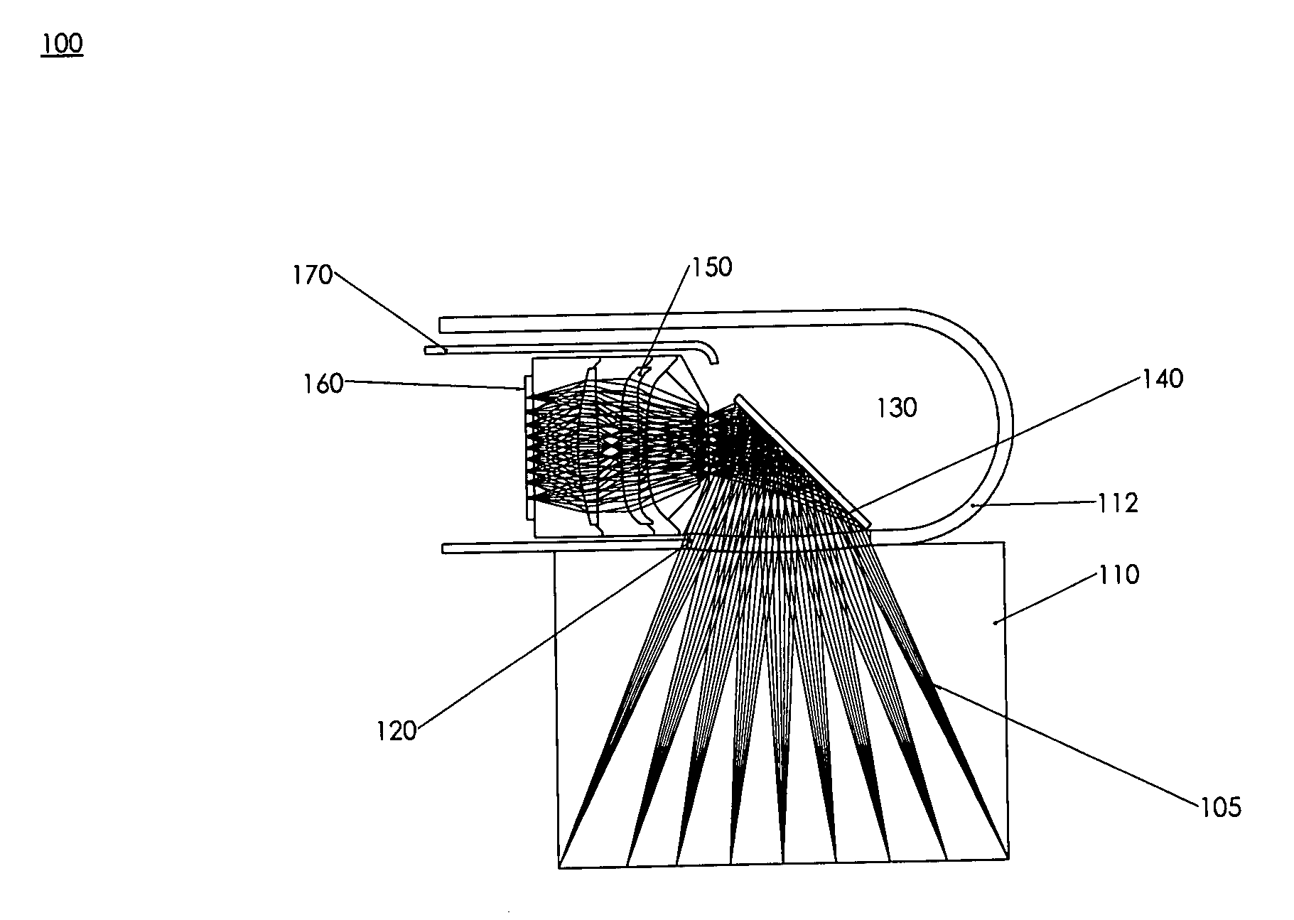
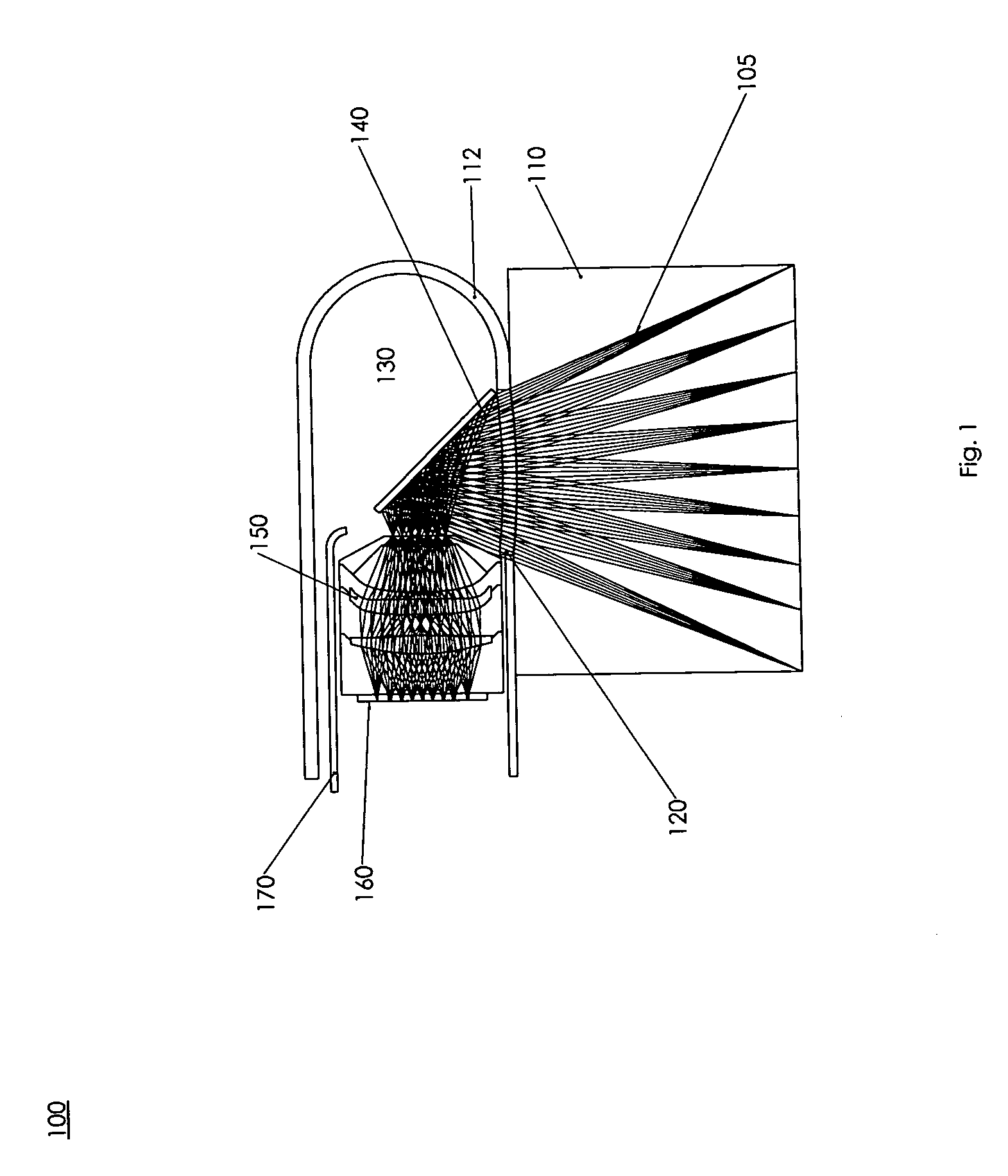
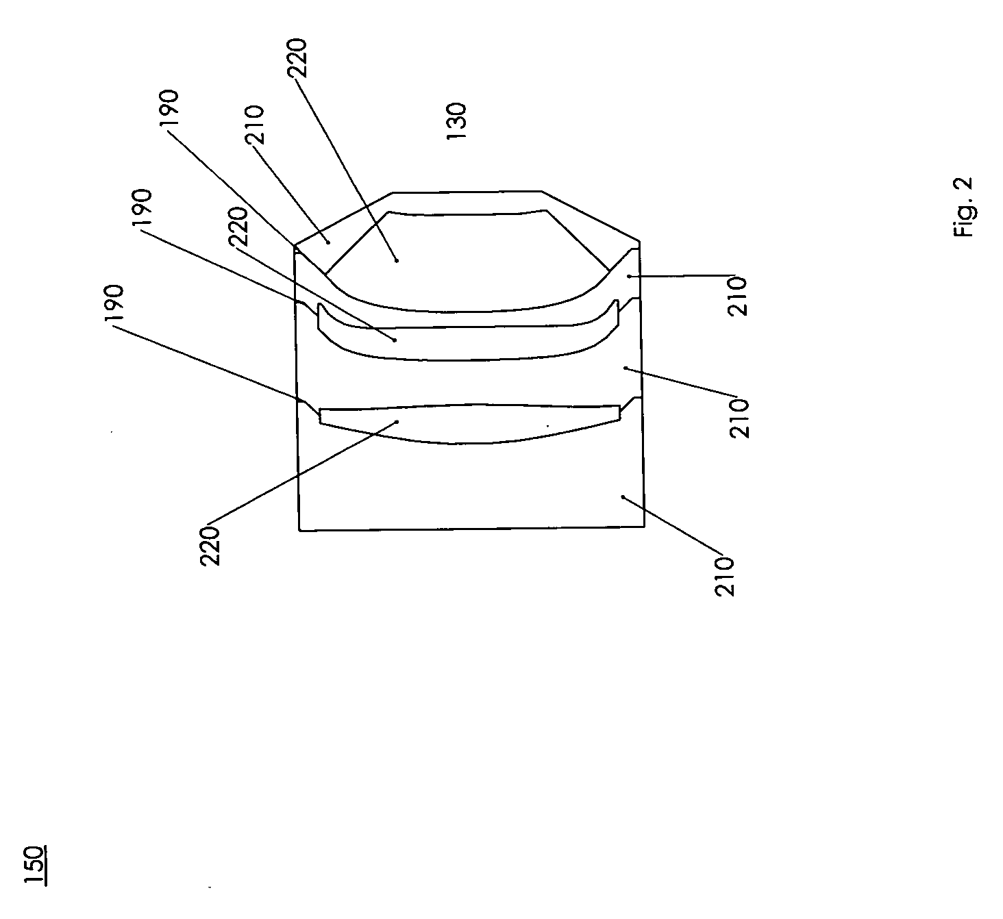
[0041]An acoustic imaging probe for use in an acoustic imaging system comprising a single cohesive composite acoustic lens, a low acoustic impedence fluid, a housing for said acoustic lens, a window through said housing, and an acoustic imager.

[0042]An acoustic imaging probe for use in an acoustic imaging system comprising a cohesive composite acoustic lens incorporating aspheric geometry and exhibiting low or practically no measurable dispersion of acoustic waves constructed of at least one material with a low acoustic impedance and attenuation and a relatively low acoustic velocity and at least one other materi...


PUM


Abstract

Various embodiments of the present invention provide for a photoacoustic imaging probe for use in a photoacoustic imaging system, whereby the probe is comprised of a cohesive composite, acoustic lens incorporating aspheric geometry and exhibiting low or practically no measurable dispersion of acoustic waves constructed of at least one material with a low acoustic impedance and attenuation and a relatively low acoustic velocity and at least one other material with a low acoustic impedance and attenuation and a relatively high acoustic velocity. The probe is housed in a conduit filled with a low acoustic velocity and low acoustic impedance fluid such as water or mineral oil. The lens may be designed as a telecentric lens, an acoustic zoom lens, a catadioptric lens, or a reflective lens. The lens focuses acoustic waves on an acoustic imager which detects the image. The acoustic imager may be designed as a 2 dimensional array of transducers. Research to date indicates that within the range of acoustic frequencies of interest, 1 MHz-50 MHz and preferable 2 MHz-10 MHz, there exists little velocity variation within the materials of interest, and the lens design approach may currently be considered to be essentially monochromatic. The acoustic waves can be generated when an emitting light source illuminates a test subject comprising materials that generate acoustic waves at differing intensities and / or frequencies when illuminated with light, for example tissue containing blood vessels, wherein the blood vessels excite and generate an acoustic pulse. The probe has an acoustic window made of a material with low acoustic impedance which allows the acoustic pulse to enter the probe without distortion and then may be reflected by a mirror onto the acoustic lens. The probe may include the emitting light source and an optical window to allow light emitting from said light source to illuminate the test subject.

Description

CROSS-REFERENCE TO RELATED PATENT APPLICATIONS[0001]Priority for this patent application is based upon provisional patent application 60 / 959,652 (filed on Jul. 16, 2007). The disclosure of this United States patent application is hereby incorporated by reference into this specification.BACKGROUND OF THE INVENTION[0002]Photoacoustic imaging is known in the literature but it is typically accomplished using a one dimensional array of detectors recording the signal from an optical transducer that generates a single pulse of 5-50 nanosecond duration. The systems that use this process are complicated to use and manufacture. These systems are not readily useful for applications such as cancer detection due to the requirements for the size of the device required to detect this acoustic chirp, and the processing power required to convert the detected signals into an image.[0003]Another method used to generate the signal for the array of detectors to record is using echo based ultrasound, and...

Claims


Application Information

Patent Timeline
Patent Type & Authority Applications(United States)
IPC IPC(8): A61B8/00
CPCA61B5/0095A61B8/12A61B8/08A61B6/466A61B8/14
Inventor ARNOLD, STEPHEN C.
Owner ARNOLD STEPHEN C
Why Eureka
Try Eureka