High-bandwidth actuator drive for scanning probe microscopy

a high-bandwidth, actuator technology, applied in the direction of material analysis using wave/particle radiation, instruments, nuclear engineering, etc., can solve the problems of signal amplifier, amplifier gain, and restrict the ability of amplifiers to drive actuators

Inactive Publication Date: 2009-02-05
BRUKER NANO INC
View PDF36 Cites 3 Cited by
  • Summary
  • Abstract
  • Description
  • Claims
  • Application Information

AI Technical Summary

Benefits of technology

[0013]The relative motion can be produced by various techniques, including moving the probe while maintaining the sample in a fixed position, or vice-versa; or moving both, the probe, and the sample. The actuator driving circuit applies a drive signal to the actuator to cause the relative motion, and has a small signal bandwidth of at least 200 kHz with a phase lag of not more than 100 degrees within the small signal bandwidth. One advantage of the actuator driving circuit that can achieve such a bandwidth such with limited phase lag while driving an actuator that can create a displacement of greater than one micron is the ability to achieve substantially improved throughput of the SPM system to previously unattainable levels.

Problems solved by technology

Achieving a high driving signal bandwidth presents a number of challenges.
This frequency compensation internal to the driving amplifier circuit substantially reduces the amplifier's gain at the high frequencies and introduces additional phase delay, thereby restricting the amplifier's ability to drive the actuator at those high frequencies, and presenting a greater contribution to the phase offset of the actuator control system.
In SPM systems, a common cause of instability in the driving signal amplifier is the actuator's reactive loading characteristics on the driving signal amplifier.
Under certain conditions, the reactive nature of this capacitive load can cause uncontrolled oscillations in the amplifier circuit.
While the load-isolating resistance beneficially stabilizes the amplifier, it does so at the cost of introducing another phase offset into the cantilever control system, further limiting the overall operating bandwidth.
Conventional general-purpose amplifiers and amplifier stabilization techniques, which are not adapted specifically for SPM applications, suffer from these, and various other shortcomings when applied to high-speed SPM applications.

Method used


Image

  • High-bandwidth actuator drive for scanning probe microscopy
  • High-bandwidth actuator drive for scanning probe microscopy
  • High-bandwidth actuator drive for scanning probe microscopy

Examples


Embodiment Construction

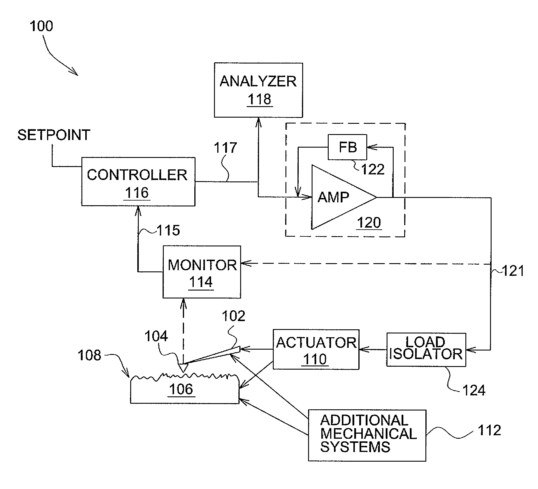
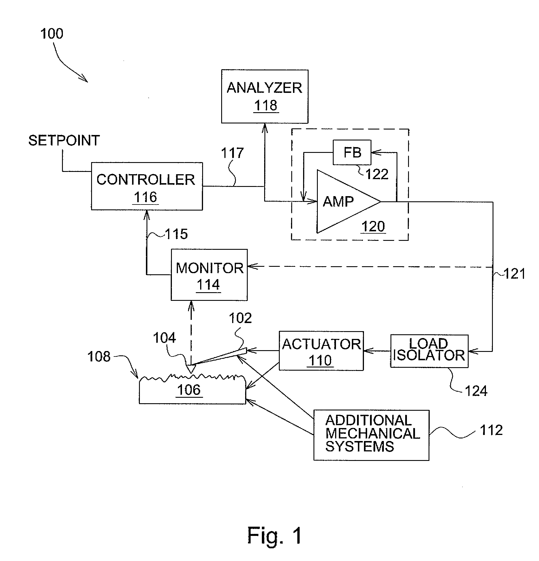
[0039]FIG. 1 is a top-level diagram illustrating a portion of a typical SPM system 100. System 100 includes cantilever 102 that holds probe 104. Probe 104 is used to inspect sample 106 having surface 108. Surface 108 has a certain topography, which is the subject of the inspection in certain applications. More generally, for samples that do not have major surfaces defined by corresponding aspect ratios, the topography of the sample can similarly be inspected by the SPM. The term topography is defined herein as a representation of a three-dimensional profile of a sample or of a portion of a sample, including, but not limited to, surface features of a sample.

[0040]The inspection is accomplished by situating probe 104 relatively to surface 108 by moving either cantilever 102, sample 106, or both, in order to establish a detectable interaction between surface 108 and probe 104. Probe 104 is scanned over or across the sample while probe 104 tracks the topography of sample 106, such as, f...


PUM


Abstract

An actuator subsystem for use in a scanning probe microscope (SPM) system having a probe for measuring a sample comprises and actuator and an actuator driving circuit. The actuator operates in the SPM system to generate relative motion between the probe and the sample while the SPM system collects data indicative of a property of the sample. The relative motion includes a range of motion of at least 1 micron. The actuator driving circuit applies a drive signal to the actuator to cause the relative motion, and has a small signal bandwidth of at least 200 kHz with a phase lag of not more than 100 degrees within the small signal bandwidth.

Description

FIELD OF THE INVENTION[0001]The present invention relates generally to scanning probe microscopy and, more particularly, to driving and controlling the probe actuator of a scanning probe microscope in at least one axis of motion.BACKGROUND OF THE INVENTION[0002]Scanning probe microscopes (SPMs), such as the atomic force microscope (AFM), are instruments which typically use a sharp tip to characterize the surface of a sample down to nanoscale dimensions. The term nanoscale as used for purposes of this invention refers to dimensions smaller than one micrometer. SPMs monitor the interaction between the sample and the probe tip. By providing relative scanning movement between the tip and the sample, surface characteristic data can be acquired over a particular site on the sample, and a corresponding map of the site can be generated. Because of their resolution and versatility, SPMs are important measurement devices in many diverse fields ranging from semiconductor manufacturing to biolo...

Claims


Application Information

Patent Timeline
Patent Type & Authority Applications(United States)
IPC IPC(8): G12B21/02G01Q10/06
CPCG01Q10/065B82Y35/00
Inventor RUSSELL, WILLIAM I.
Owner BRUKER NANO INC
Why Eureka
Try Eureka