Focused negative ion beam field source

a negative ion beam and field source technology, applied in the direction of ion beam tubes, instruments, heat measurement, etc., can solve the problems of limiting the focusing capability of the focused ion beam system, introducing some difficulties in the source implementation, and a relatively small number of metallic elements and alloys can be used successfully

Active Publication Date: 2009-02-05
MASSACHUSETTS INST OF TECH
View PDF2 Cites 20 Cited by
  • Summary
  • Abstract
  • Description
  • Claims
  • Application Information

AI Technical Summary

Benefits of technology

[0010]In one aspect, the invention includes an apparatus for producing negative ions. The invention includes an emitter coated with an ionic liquid room-temperature molten salt. An electrode is positioned downstream relative to the emitter. A power supply applies a

Problems solved by technology

These problems range from limiting the focusing capabilities of the focused ion beam system to surface damage due to differential charging.
Except for metals such as In or Ga, most sources work only at very high temperatures, thus introducing some difficulties in the source implementation, as the thermal evaporation rate of neutrals increases and chemical reactions with the needle material (e.g., tungsten) may occur.
These thermal and compatibility issues mean that only a relatively small number of metallic elements and alloys can be successfull

Method used


Image

  • Focused negative ion beam field source
  • Focused negative ion beam field source
  • Focused negative ion beam field source

Examples


Embodiment Construction

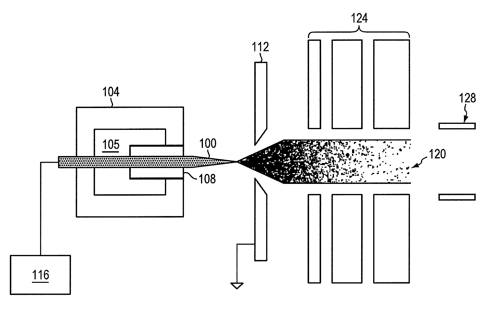
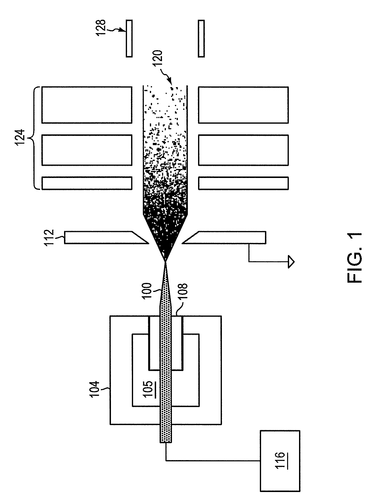
[0034]FIG. 1 is a schematic of a focused negative ion beam source, according to an illustrative embodiment of the invention. A negative ion beam source can include an emitter 100 coated (e.g., externally wetted) with an ionic liquid room-temperature molten salt, an electrode 112 positioned downstream relative to the emitter 100 and a power supply 116 that applies a voltage to the emitter 100 with respect to the electrode 112, sufficient to generate a stable high brightness beam 120 of negative ions (e.g., negative ions or a substantially monoenergetic heavy ion beam) having minimal chromatic and spherical aberrations in the beam. The ion source can also include an electrostatic lens 124 and a deflector 128 to focus and direct the beam 120 to a target.

[0035]The emitter 100 can be mounted on a dielectric enclosure 104. In some embodiments, the dielectric enclosure 104 is made of plastic or a ceramic. In this embodiment, the dielectric enclosure 104 includes a vacuum 105. A cylinder 10...


PUM


Abstract

An apparatus for producing negative ions including an emitter coated with an ionic liquid room-temperature molten salt, an electrode positioned downstream relative to the emitter, a power supply that applies a voltage to the emitter with respect to the electrode. The power supply is sufficient to generate a stable high brightness beam of negative ions having minimal chromatic and spherical aberrations in the beam. An electrostatic lens and deflector is used to focus and direct the beam to a target.

Description

CROSS-REFERENCE TO RELATED APPLICATION[0001]This application claims the benefit of and priority to U.S. provisional patent application 60 / 942,846 filed on Jun. 8, 2007, which is owned by the assignee of the instant application and the disclosure of which is incorporated herein by reference in its entirety.GOVERNMENT SUPPORT[0002]The subject matter described herein was supported in part by the Air Force Office of Scientific Research, Contract No. F49620-01-1-398. The U.S. Government has certain rights in this technology.FIELD OF THE TECHNOLOGY[0003]The technology generally relates to devices and methods of generating ions to a target. In particular, the technology relates to an apparatus to generate a stable beam of negative ions having minimal aberrations in the beam.BACKGROUND OF THE INVENTION[0004]Ionic liquids are used in ionic liquid ion sources. Ionic liquid ion sources are impregnated with solvent-free ionic liquids, also known as room temperature molten salts. Ionic liquids a...

Claims


Application Information

Patent Timeline
IPC IPC(8): H01J3/18
CPCH01J27/028H01J27/26H01J37/08H01J2237/31749H01J2237/08H01J2237/0815H01J2237/0827H01J2237/0048
Inventor LOZANO, PAULOMARTINEZ-SANCHEZ, MANUEL
Owner MASSACHUSETTS INST OF TECH
Why Eureka
Try Eureka