Method for forming image pattern on surface of metallic glass member, apparatus for forming image pattern, and metallic glass member having image pattern on its surface

a technology of image pattern and metallic glass, which is applied in the field of method for forming image pattern on the surface of metallic glass member, apparatus for forming image pattern, and metallic glass member, can solve the problems of inability to use the method for forming metallic glass and metal, a large number of devices, and large amount of machining time, etc., to achieve simple operation steps and efficiently form the pattern.

Inactive Publication Date: 2009-02-19
NGK INSULATORS LTD
View PDF4 Cites 7 Cited by
  • Summary
  • Abstract
  • Description
  • Claims
  • Application Information

AI Technical Summary

Benefits of technology

[0025]The method or the device of the present invention has made it possible to form a pattern efficiently with positional accuracy onto metallic glass, especially even onto Zr based, Ti based, Cu based, Ni based and Fe based metallic glass, which have supercooled liquid temperature ranges of not lower than 400° C. and are also required to be press-formed at not lower than 400° C., in large number with the simple operating steps required for pattern formation.

Problems solved by technology

There have been problems with the conventional image pattern forming methods as below.
(a) First, in the method of laser marking directly onto the product shown in Patent Documents 1 and 2, to inscribe a fine pattern onto a large number of products with positional accuracy, a large amount of machining time and a large number of devices to execute the operation are required, and consequently, operating efficiency becomes worse.
But this method could not be used for forming a metallic glass and a metal.
But a large number of mold producing steps requires taking a long period of time, it makes the cost of the mold high accordingly.
Further, the mold for Ni electro forming can be used for a Pd based metallic glass, which has a low supercooled liquid temperature range and is press-formed at not higher than 400° C. But the mold cannot be used for Zr based, Ti based, Cu based, Ni based and Fe based metallic glass, which supercooled liquid temperature ranges are not lower than 400° C.
), and consequently, the strength of the mold is insufficient.

Method used


Image

  • Method for forming image pattern on surface of metallic glass member, apparatus for forming image pattern, and metallic glass member having image pattern on its surface
  • Method for forming image pattern on surface of metallic glass member, apparatus for forming image pattern, and metallic glass member having image pattern on its surface
  • Method for forming image pattern on surface of metallic glass member, apparatus for forming image pattern, and metallic glass member having image pattern on its surface

Examples


Embodiment Construction

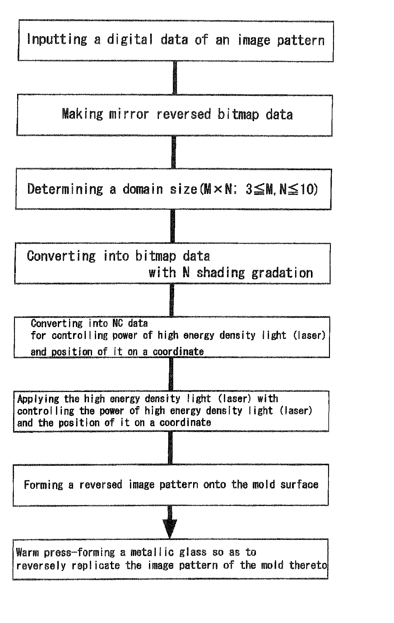
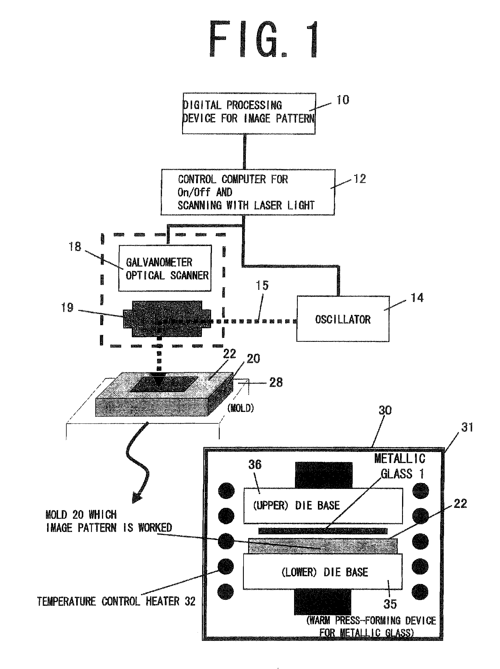
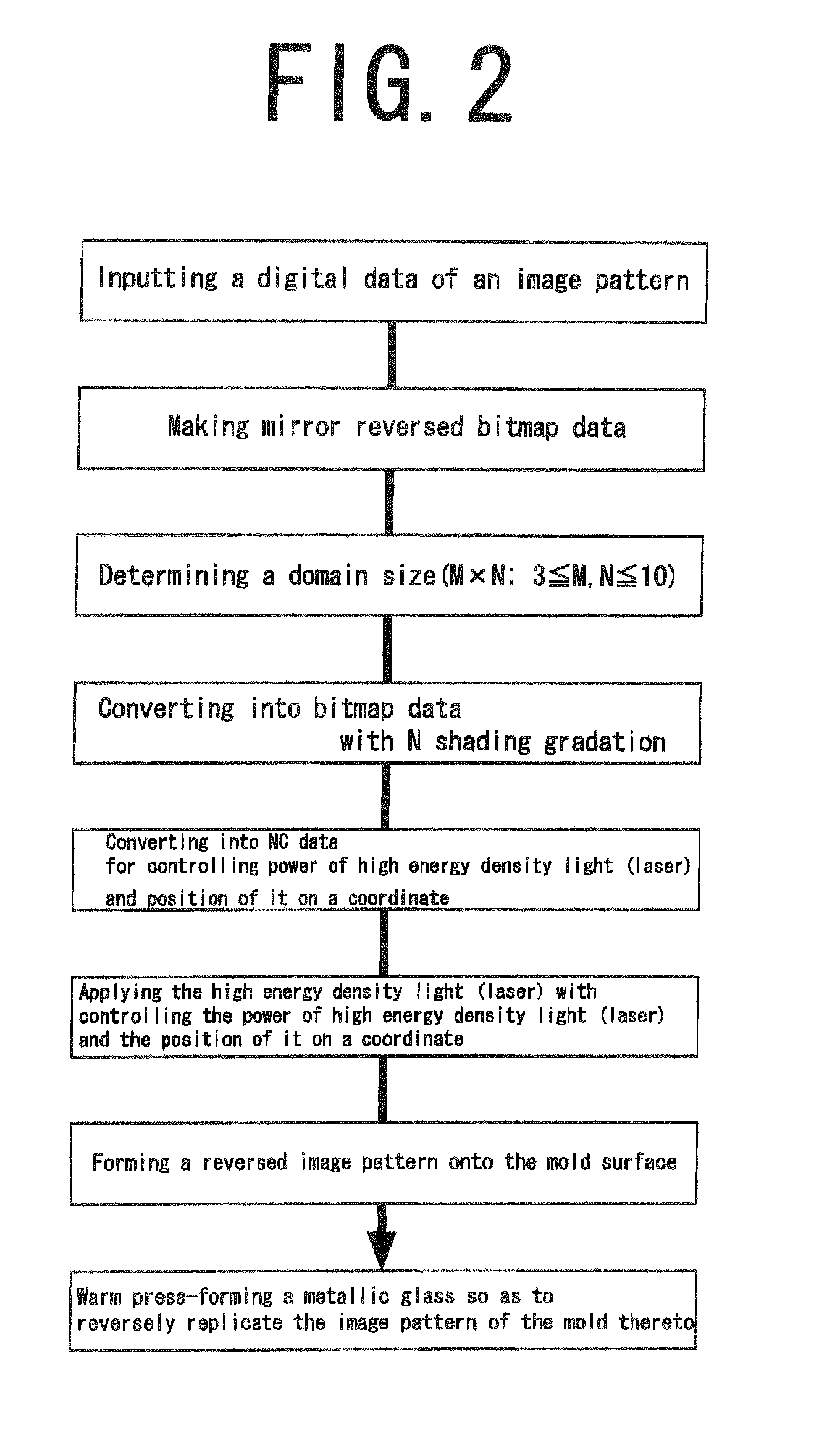
[0031]A preferred embodiment of the present invention is described below. FIG. 1 is a basic device configuration of the present invention. FIG. 2 is a process chart showing a flow of a basic process of the present invention, where the following procedure has been adopted: “inputting a digital data of an image pattern”→“making mirror reversed bitmap data”→“determining a domain size”→“converting into bitmap data with N shading gradation”→“converting into NC data for controlling power of high energy density light (laser) and position of it on a coordinate”→“applying the high energy density light (laser) with controlling the power of high energy density light (laser) and the position of it on a coordinate”→“forming a reversed image pattern onto the mold surface”→“warm press-forming a metallic glass so as to reversely replicate the image pattern of the mold thereto”. Further, as described later, “determining a domain size”→“converting into bitmap data with N shading gradation” may be del...


PUM

PropertyMeasurementUnit
lengthaaaaaaaaaa
lengthaaaaaaaaaa
depthaaaaaaaaaa

Abstract

A challenge of the present invention is to develop a method for repeatedly forming a reverse transferred pattern in a simple and efficient manner onto the surfaces of Zr based, Ti based, Cu based, Ni based and Fe based metallic glass that have supercooled liquid temperatures of not lower than 400° C. and are also required to be molded at not lower than 400° C. (a) An image pattern is converted into bitmap data being mirror reversed with respect to a real image, (b) high energy density light 15 is repeatedly flashed, and the surface of a mold 20 is scanned while one of dot holes 24 is formed by one-time irradiation, to form an image pattern as dots assembled pattern 21 onto the surface of the mold 20 in accordance with the bitmap data, and (c) the dots assembled pattern 21 is reverse-transfer molded onto a metallic glass 1 within a supercooled liquid temperature range Tg-Tx by means of the mold 20 which is for dots assembled pattern formation.

Description

BACKGROUND OF THE INVENTION[0001]1. Field of the Invention[0002]The present invention relates to an image pattern forming method used for forming a design onto a surface of metallic glass or for adding a decorative pattern, an image, a letter to the surface of the metallic glass (e.g. a mechanical component), a device for forming the image pattern, and a metallic glass with the image pattern formed onto the surface thereof.[0003]2. Description of the Related Art[0004]In order to form a surface design of a resin-made mechanical product, a photographic image has been directly inscribed by laser marking on a product (e.g. Patent Document 1: Japanese Patent Laid-Open Application No. 2005-152968, “Image marking device for cellular phone” Techno Polymer Co., Ltd.). Image drawing onto a metal surface by laser processing as above is introduced in Patent Document 2 (Japanese Patent Laid-Open Application No, 2004-115901, “Method for forming picture onto aluminum alloy surface” AISIN KEIKINZOK...

Claims


Application Information

Patent Timeline
Patent Type & Authority Applications(United States)
IPC IPC(8): B22C9/00B22C7/00B22C9/12B23K26/38
CPCB22D23/00B23K26/0084B23K26/409B44C1/228B23K2203/04B23K2203/08B23K2201/20B23K26/355B23K26/40B23K2101/20B23K2103/02B23K2103/04B23K2103/08B23K2103/12B23K2103/14B23K2103/172B23K2103/26
Inventor INOUE, AKIHISAWANG, XIN MINMURAMATSU, NAOKUNIKONDO, YOSHIMASAKATO, KENJI
Owner NGK INSULATORS LTD
Why Eureka
Try Eureka