
Cornu's Spiral Tooth Gear

a gear and spiral technology, applied in the direction of gearing elements, belts/chains/gearrings, hoisting equipments, etc., can solve the problems of wear and pitting, difficult to perform smooth working rotation, and dedendum tend to break, so as to achieve smooth steering operation and excellent characteristics. , the effect of good stability

Active Publication Date: 2009-02-26
MIYAOKU TSUTOMU +2
View PDF7 Cites 10 Cited by
  • Summary
  • Abstract
  • Description
  • Claims
  • Application Information

AI Technical Summary

Benefits of technology

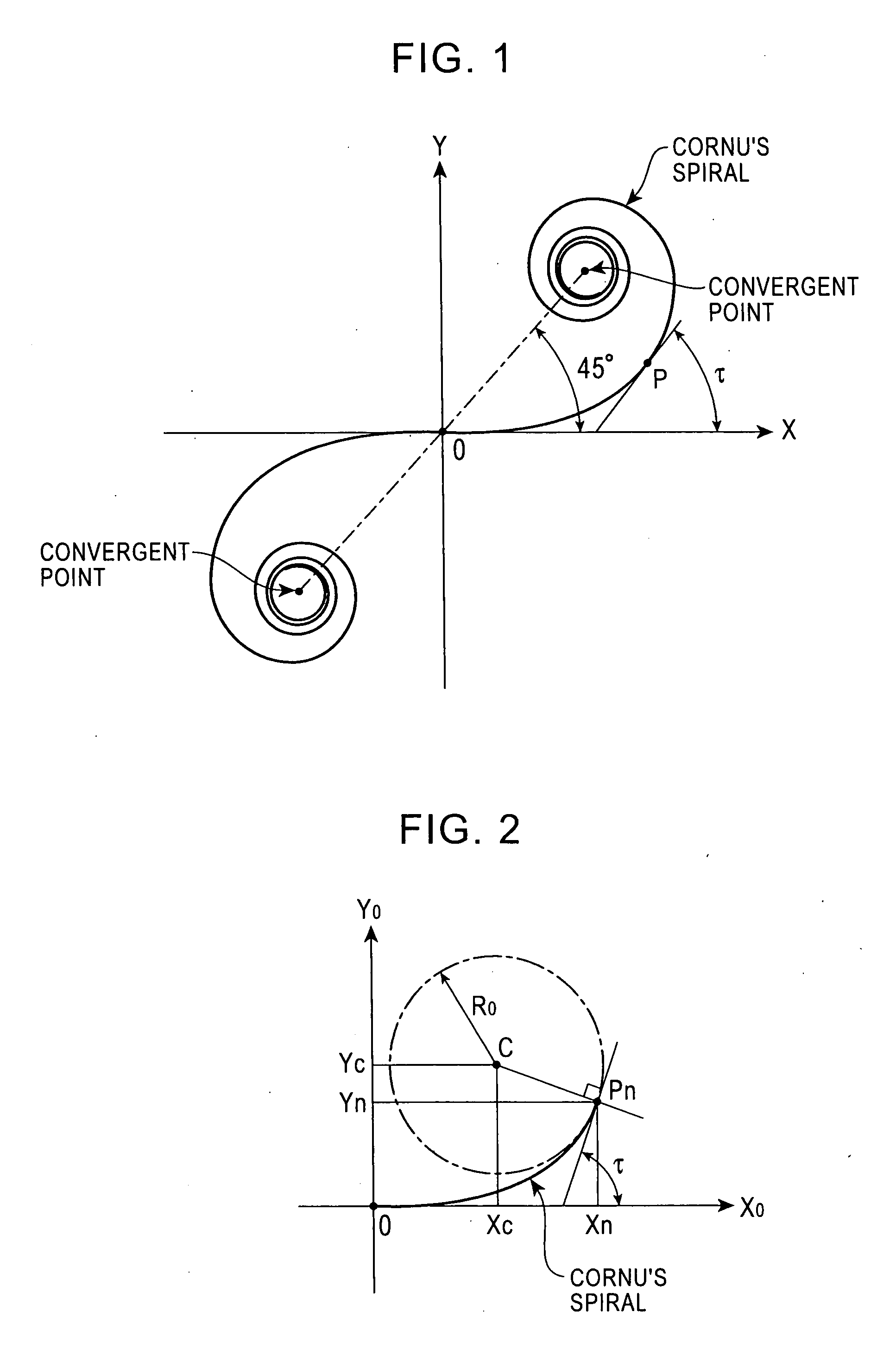
[0008]Until now, the present inventor et al. investigated various curves that are not used as tooth profiles and have tried to apply them as tooth profiles. The investigation results show that a gear having a Cornu's spiral as a tooth profile has excellent characteristics that are not provided by related tooth profiles, as a result of which this invention is achieved. As shown in FIG. 1, a Cornu's spiral. is known as a curve whose curvature constantly increases and decreases at a constant rate in proportion to a length measured along the curve, and which converges at certain points. An industrial application of the Cornu's spiral is a clothoid curve in a civil engineering structure. The clothoid curve is also called a transition curve, and allows a smooth, safe steering operation when switching from a high-speed travel path having a small curvature to a low-speed guide path having a large curvature. The mathematics of the clothoid curve is discussed in detail in, for example, “Design and Setting of a Clothoid Curve” by Yataro Kanai. The present inventor et al. have manufactured a gear by way of trial using the basic-figure solving method disclosed in this document.

Problems solved by technology

They are (1) during use, the slippage ratio at a tooth flank is large, thereby causing the tooth flank to wear often, (2) since protrusion flanks engage each other, contact surface pressure of the flanks of teeth is large, thereby causing wearing and pitting to occur often, (3) since stress at a dedendum based on the dedendum profile is large, the dedendum tends to break due to a high load and shock, (4) undercutting occurs in the dedendum when the number of teeth is less than or equal to a certain number of teeth during hob cutting process, (5) actually, unless there is proper backlash, it is difficult to perform smooth working rotation, and (6) a noise level that is generated during operation by, for example, vibration of a tooth or backlash is high.
Moreover, since an error in the distance between centers of a pair of gears caused by an assembly error cannot be prevented from occurring, this modification processing has almost no effect.
However, the WN gear cannot transmit rotation unless it is a helical gear.
In addition, vibration and noise are high, as a result of which the WN gear is rarely put into practical use at intermediate and high-speed regions.
However, they do not disclose a specific differential formula and a periodical increase / decrease rate of curvature change, which are required for forming a realistic basic tooth profile curve.

Method used


Image

  • Cornu's Spiral Tooth Gear
  • Cornu's Spiral Tooth Gear
  • Cornu's Spiral Tooth Gear

Examples


example 1

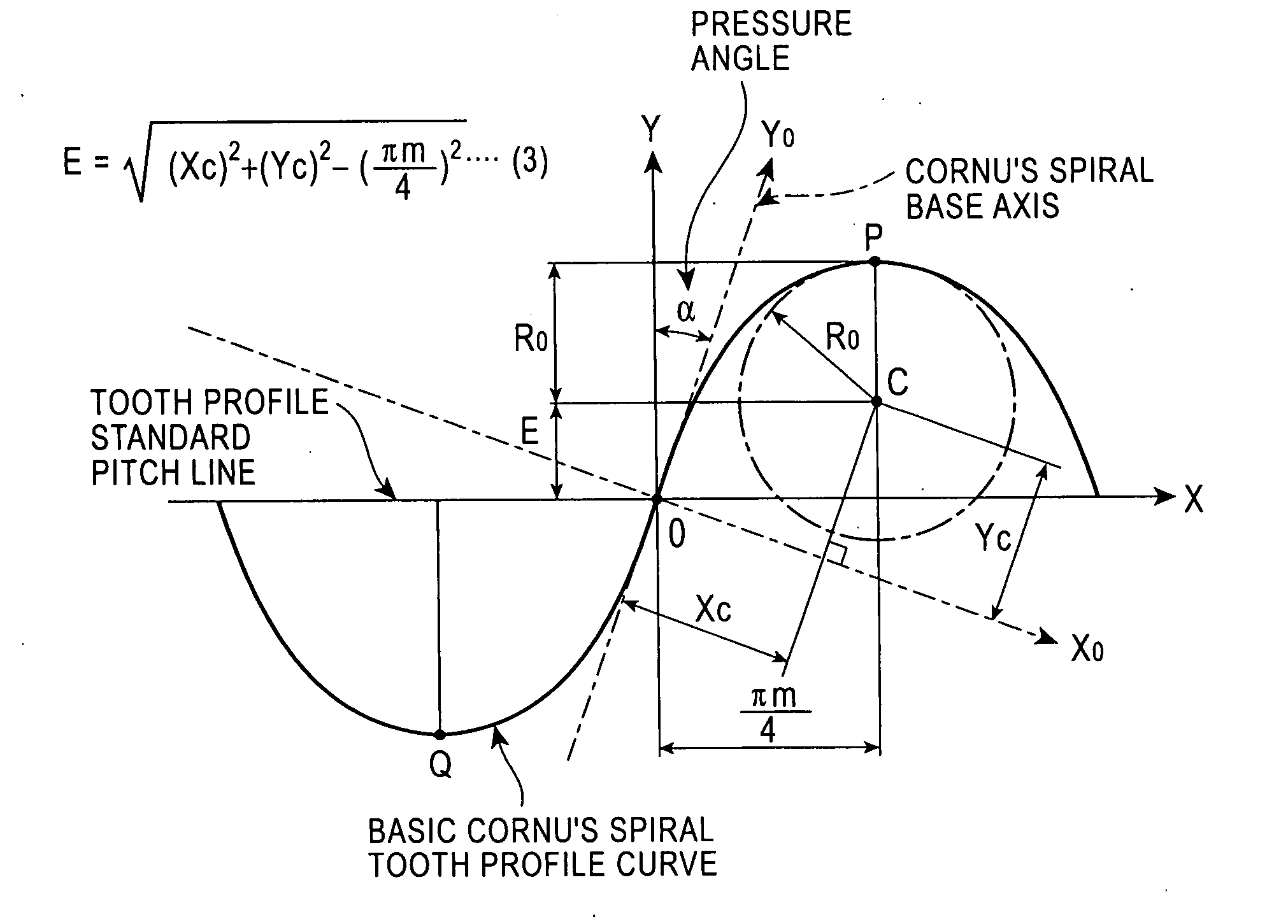
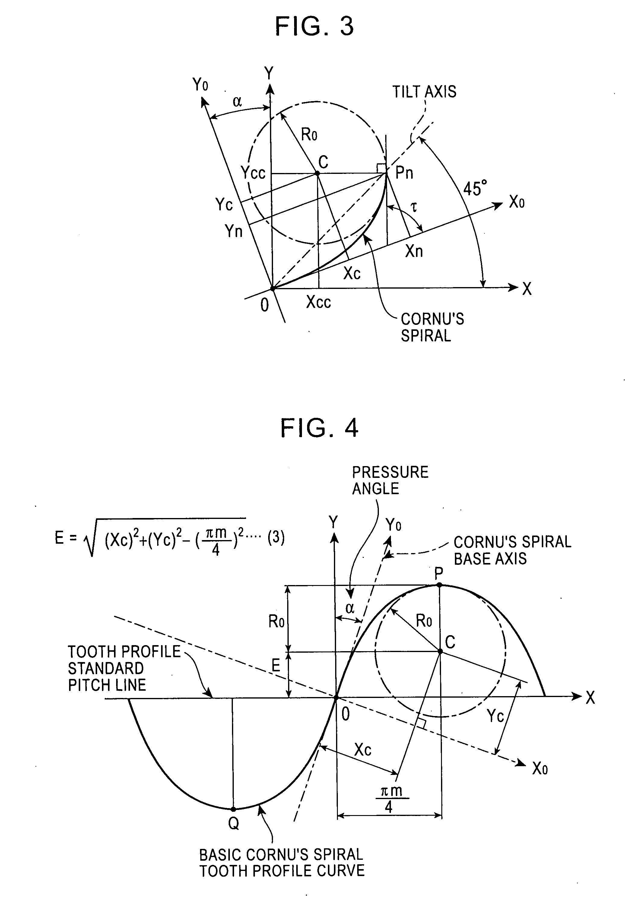
[0047]The inventor et al. manufactured two spur gears where module m=3, the pressure angle α=20 degrees, and the number of teeth Z=18. Data indicating that R0=1.80 mm and Yc=1.989 mm was obtained from FIG. 5, to determine a basic Cornu's spiral tooth profile, and a wire cut electric spark machine based on a numerical control method was used to cut out and manufacture the gears from high-carbon steel. Here, the inventor et al. completed a computer program for forming a profile of a generative gear using figure data of the basic tooth profile. One of the gears manufactured in this way was fitted to a driving shaft, and the other gear was fitted to a driven shaft, so that both of the gears were engaged and rotated. FIG. 12 is an enlarged partial view of a working state. A pair of involute tooth gears having the same module were manufactured using the same material and processing method, and were similarly tested. The result confirms that the Cornu's spiral tooth gears according to the ...

example 2

[0048]One primary cause of noise that is generated when gears are engaged and driven is based on a combination of tooth profiles of the gears at a starting point of working of a dedendum of the drive gear and the tip portion of a tooth of the driven gear. Considering this point, the inventor et al. manufactured an involute tooth gear and Cornu's spiral tooth gears having various tooth profiles (such as various pressure angles, addendum lengths, dedendum lengths, and profiles of the tip portions of teeth) as a result of using the same module and the same number of teeth and the same material and processing method as those of the basic Cornu's spiral tooth gears according to Example 1. Working running tests of the gears having different tooth profiles were carried out under the same test conditions. The result confirms that, as shown in Table 1, there are Cornu's spiral tooth gears generating less noise than the involute tooth gear.

[0049]In the examples, the Cornu's spiral tooth profi...


PUM


Abstract

A Cornu's spiral is applied to a tooth profile of a gear. In accordance with the application of the gear, the Cornu's spiral may be modified two-dimensionally by some constant proportion. Since Cornu's spirals have similarity are similar, when a pressure angle is determined, the tooth profile can be standardized by a module, so that it is highly versatile.By replacing the tip of a tooth and the bottom of a tooth by another curve, such as an arc, the range of application can be increased. Since working is always by flank contact between a protrusion and a recess, contact surface stress is low. In addition, the radius of curvature of a dedendum is large. Therefore, tooth bending stress is low, and fatigue strength is high. Even if the number of teeth is small, an undercut is not produced. Even if there is no backlash, a smooth working is achieved, so that the tooth profile is suitable for devices requiring precise alignment.

Description

TECHNICAL FIELD [0001]The present invention relates to a basic tooth profile of a gear including a rack and a pinion (hereunder referred to generically as “gear”). The present invention provides a novel tooth profile curve that can reduce vibration and noise of the gear, reduce wear of a tooth flank, and increase bending strength and contact surface strength of a tooth.BACKGROUND ART[0002]At present, the most generally used basic tooth profile for a gear is an involute tooth profile, and is used in various mechanical devices of the industrial society. The main advantages include the following four points. They are (a) transmission rotation is performed at a constant velocity ratio, (b) generative processing with a hob cutter is easily carried out, (c) even if a slight error occurs in the precision with which a tooth profile is processed or the precision with which a gear system is assembled, this error does not, practically speaking, adversely affect the transmission of rotation, an...

Claims


Application Information

Patent Timeline
IPC IPC(8): F16H55/08
CPCY10T74/19972F16H55/08
Inventor MIYAOKU, TSUTOMUKANEHIRO, JIROSASAKI, HIDEKAZU
Owner MIYAOKU TSUTOMU
Learn More