
Enhanced Magnetic Plating Method and Apparatus

Inactive Publication Date: 2009-02-26
GLOBALFOUNDRIES INC
View PDF5 Cites 5 Cited by
  • Summary
  • Abstract
  • Description
  • Claims
  • Application Information

AI Technical Summary

Benefits of technology

[0014]According to an embodiment of the present invention, a tool for plating a magnetic film on a substrate includes: a track including a plurality of stopping points along the track; a permanent magnet placed on the track such that the permanent magnet can be moved along the track towards and away from the stopping points along the track; at least one plating tank positioned on the stopping point along the track; and a removable high permeability iron flux concentrator inserted into gaps between the substrate and inside walls of the plating tank, substantially surrounding the substrate and extending around and under the substrate. The method can also include a removable electroplating anode. According to another embodiment, the removal of the electroplating anode is facilitated by moving the permanent magnet away from the stopping point where the magnet is positioned close to the anode.
[0015]According to another embodiment of the present invention, a method for plating magnetic film on a substrate includes: mounting a permanent magnet on a track including a plurality of stopping points, wherein the permanent magnet is movable along the track; positioning a first cell on a first stopping point; positioning a second cell on a second stopping point; and moving the permanent magnet along the track to the first and second stopping points wherein the magnet surrounds the first and second cells, respectively, when positioned; and wherein the permanent magnet magnetizes the substrate disposed within the first and second cells. Further, a conformable magnetic material is introduced into the first and second cells, substantially surrounding the substrate. Further, the removal and insertion of a plating anode may be facilitated by repositioning the permanent magnet.

Problems solved by technology

In the semiconductor industry the wafer size on which devices are fabricated has been steadily increasing, which has resulted in a dramatic decrease of cost per unit cell.
Some assistance in overcoming the demagnetizing field is achieved by plating magnetic films through narrow photo resist frames providing pseudo continuous film but even that is not sufficient when the dimensions of the pattern become very small and at the same time it is necessary to make films relatively thick.
The demagnetizing field at such edges, unless the films are laminated by a non-magnetic material, can reach the value of the saturation magnetization of the film and it becomes very difficult to achieve any degree of the intrinsic magnetic anisotropy in the deposited magnetic films.
Using even the highest commercially available permanent magnets it has not been possible to achieve 1000 Oe in the middle of a plating tank capable of accommodating an 8-inch wafer.
Electromagnets are much more costly than permanent magnets, much too big (they occupy ten to twenty times the volume of the permanent magnet), and they require such a high current and dissipate so much heat that it is necessary to water cool the magnet.
The electromagnets also require a much higher operating cost (cost of high current electricity and of the cooling water).
This introduces a major limitation in the field strength and uniformity for magnets of reasonable cost with available hard magnet materials.
Another drawback with permanent magnets is that the magnets are expensive and the magnetic field interferes with the insertion and removal of the anode, which is usually a magnetic material such Nickel or Cobalt.
The drawback is that yet another magnet is needed for the annealing station.

Method used


Image

  • Enhanced Magnetic Plating Method and Apparatus
  • Enhanced Magnetic Plating Method and Apparatus
  • Enhanced Magnetic Plating Method and Apparatus

Examples


Embodiment Construction

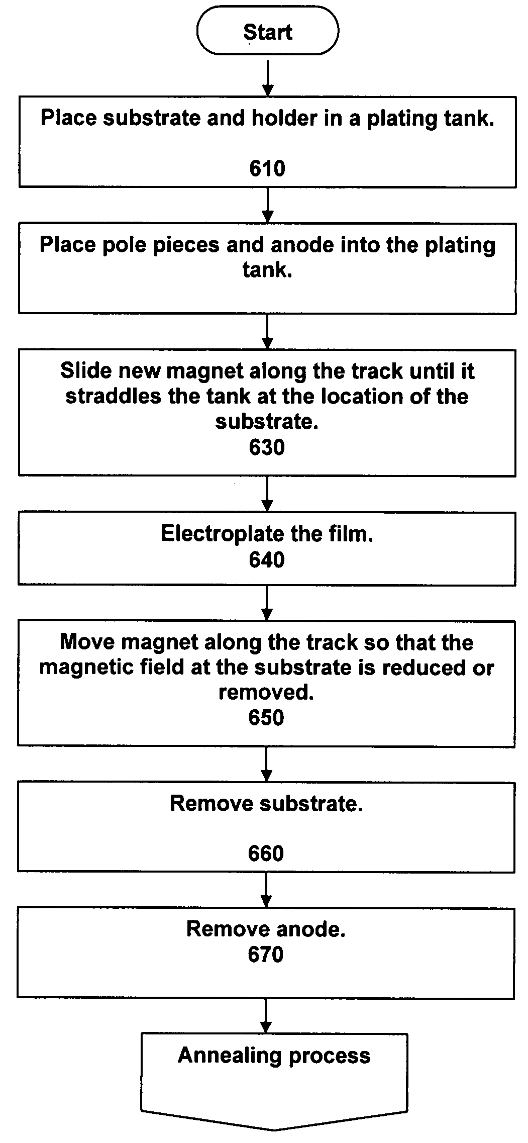
[0028]We describe a tool and method for enhancing a magnetic field used in the plating of magnetic film. This tool and method overcomes the shortcomings of the prior art by increasing the magnetic field around a wafer. This in turn enables the use of a larger wafer, with no subsequent loss of magnetic strength as measured in oresteds (Oe). Also by improving the magnetic flux distribution, we achieve better magnetic orientation and magnetic anisotropy, thereby improving the operation of the magnetic heads. The increase in wafer size yields an increase in the number of magnetic heads which can be produced, while at the same time reducing manufacturing costs. The embodiments of the proposed tool and method, as will be described fully herein, can be advantageously used in any process involving the plating of magnetic films where an applied magnetic field is desired during plating, such as tape head manufacturing. For clarity, however, we focus our discussion on wafers in the fabrication...


PUM


Abstract

An apparatus for plating a magnetic film on a substrate includes: a track including a plurality of stopping points along the track; a permanent magnet placed on the track such that the permanent magnet can be moved along the track towards and away from the stopping points; at least one plating tank positioned on the stopping point; and a removable high permeability iron flux concentrator inserted into gaps between the substrate and inside walls of the plating tank, substantially surrounding the substrate and extending around and under the substrate.

Description

CROSS-REFERENCE TO RELATED APPLICATIONS[0001]None.STATEMENT REGARDING FEDERALLY SPONSORED-RESEARCH OR DEVELOPMENT[0002]None.INCORPORATION BY REFERENCE OF MATERIAL SUBMITTED ON A COMPACT DISC[0003]Not Applicable.FIELD OF THE INVENTION[0004]The invention disclosed broadly relates to the field of magnetic film plating and more particularly relates to scalable magnetic film plating.BACKGROUND OF THE INVENTION[0005]In the semiconductor industry the wafer size on which devices are fabricated has been steadily increasing, which has resulted in a dramatic decrease of cost per unit cell. The maximum size of wafers used in the fabrication of magnetic thin film heads has remained a steady size, between five and six inches in diameter, for many years. One of the key reasons for this is that it is necessary to provide a 1000 oersted (Oe) magnetic field at the center of the wafer during plating and also during annealing to overcome the demagnetizing field in the individual tiny devices and to ach...

Claims


Application Information

Patent Timeline
IPC IPC(8): C25D5/00C25D17/00
CPCC25D17/00H01F41/26C25D5/006C25D17/02Y10S204/05C25D17/001C25D17/007Y10S204/07C25D5/009
Inventor FLOTTA, MATTEOROMANKIW, LUBOMYR TARASSHAO, XIAOYANSTEEN, STEVEN ERIKWEBB, BUCKNELL CHAPMAN
Owner GLOBALFOUNDRIES INC
Features
  • Generate Ideas
  • Intellectual Property
  • Life Sciences
  • Materials
  • Tech Scout
  • Unparalleled Data Quality
  • Higher Quality Content
  • 60% Fewer Hallucinations
Learn More