Process for Removing Silica in Heavy Oil Recovery

a technology of heavy oil and silica, which is applied in the direction of quarries, waste water treatment from quarries, chemistry apparatus and processes, etc., can solve the problems of difficult water treatment to prepare steam for steam generation, difficult silica-based compounds to foul evaporators, and high viscosity, so as to prevent the silica scaling of the evaporator surface and prevent the effect of evaporator scaling

Active Publication Date: 2009-03-05
VEOLIA WATER TECH INC
View PDF16 Cites 39 Cited by
  • Summary
  • Abstract
  • Description
  • Claims
  • Application Information

AI Technical Summary

Problems solved by technology

However, conventional oil recovery processes do not work well for higher viscosity, or heavy, oil.
Treating the produced water to prepare feed water for steam generation is challenging.
However, the produced water typically contains significant amounts of silica-based compounds.
These silica-based compounds will tend to foul evaporator and other process surfaces by scaling or deposition of silica on the surfaces.
These scales reduce the conductivity of heat transfer elements in the equipment and thus reduce the efficiency of evaporation and steam generation.
There are drawbacks and disadvantages to the current processes.
The addition of caustic to raise the pH represents a significant operating cost.
The high concentration of caustic is typically not desirable in waste streams.
Additionally, while the mechanical vapor compression evaporator recovers approximately 95% of the water from the produced water, the remaining concentrate stream is difficult to process.
Neutralizing the stream causes the precipitation of solids, and these solids are very difficult to separate from the aqueous solution.
These systems tend to be expensive to operate and costly to maintain.
This creates the potential for hardness scaling of the evaporator heat transfer surfaces if not controlled.
At this time, it does not appear that it has been determined how much hardness can be controlled using a dispersant since few existing heavy oil recovery operating systems have very low hardness in the produced water.
The higher pH processes with dispersant may not be effective in produced water having a significant hardness concentration.
Operating experience is limited for this brine treatment process, but frequent plugging of equipment and lines has been reported.
If the high pH brine is to be deep well injected, the treatment process is difficult, costly and unreliable.
However, this option is significantly more expensive than deep well injection.

Method used


Image

  • Process for Removing Silica in Heavy Oil Recovery
  • Process for Removing Silica in Heavy Oil Recovery
  • Process for Removing Silica in Heavy Oil Recovery

Examples


example

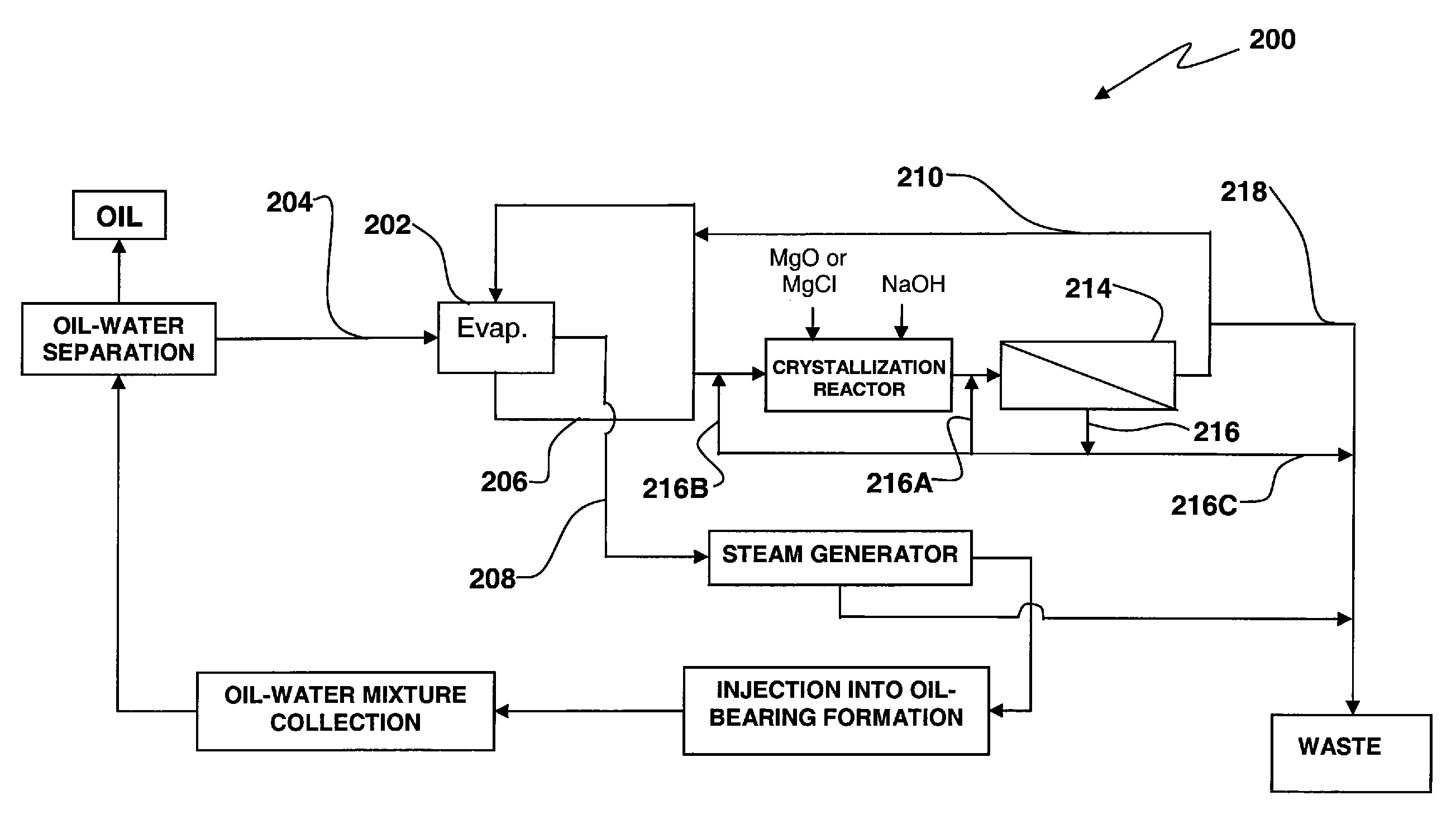
[0048]A pilot scale test was performed on a produced water sample. The objective of the test was to determine scaling tendency. Dosages of magnesium oxide and sodium hydroxide were mixed with the produced water to simulate the sorption slurry process. The test was performed at a recovery of approximately 97%, meaning that the mass per unit of time of the distillate produced by the single evaporator used was approximately 97% of the mass per unit time of the produced water feed to the evaporator 202. The pilot testing was performed using a single tube falling film evaporator comprising a vapor body, a falling film heat exchanger, brine recirculation pump with variable speed drive, surface condenser for process vapors, steam and process condensate receivers, feed tank, and a feed pump with a variable speed drive.

[0049]The feed used for the pilot test was a produced water sample. An analysis of the produced water sample is provided in Table 1 below.

TABLE 1DescriptionUnitsFeed for 97% R...


PUM


Abstract

A process for recovery oil includes recovering an oil / water mixture from an oil well. Thereafter, the method includes separating oil from the oil / water mixture to produce an oil product and produced water having dissolved silica therein. The produced water is directed to an evaporator and produces steam and a concentrated brine. The method or process entails mixing a precipitant or crystallizing reagent with the produced water or the concentrated brine and causing the silica to precipitate from the produced water or the concentrated brine. Steam produced by the evaporator is condensed to form a distillate which is directed to steam generator. At the steam generator the distillate is heated to produce steam which is injected into an injection well, giving rise to the formation of the oil / water mixture.

Description

CROSS-REFERENCE TO RELATED APPLICATION[0001]This application claims priority under 35 U.S.C. §119(e) from the following U.S. provisional application: Application Ser. No. 60 / 968,180 filed on Aug. 27, 2007. That application is incorporated in its entirety by reference herein.FIELD OF INVENTION[0002]The present invention relates to a process for recovering heavy oil, and more particularly, to an oil recovery process that utilizes a mechanical vapor compression evaporation system to treat produced water.BACKGROUND[0003]Conventional oil recovery involves drilling a well and pumping a mixture of oil and water from the well. Oil is separated from the water, and the water is usually injected into a sub-surface formation. Conventional recovery works well for low viscosity oil. However, conventional oil recovery processes do not work well for higher viscosity, or heavy, oil.[0004]Enhanced Oil Recovery processes employ thermal methods to improve the recovery of heavy oils from sub-surface res...

Claims


Application Information

Patent Timeline
Patent Type & Authority Applications(United States)
IPC IPC(8): E21B43/24
CPCE21B43/34E21B43/24C02F1/048C02F2103/10E21B43/35
Inventor MINNICH, KEITH R.PETERSON, DAN
Owner VEOLIA WATER TECH INC
Why Eureka
Try Eureka