Apparatus and Method for Peak Suppression in Wireless Communication Systems

a communication apparatus and wireless communication technology, applied in multi-frequency code systems, transmission path sub-channel allocation, baseband system details, etc., can solve the problems of large characteristic degradation and large communication characteristics degradation, and achieve the reduction of peak-to-average power ratio (papr), reduce power consumption, and limit communication characteristics degradation

Inactive Publication Date: 2009-03-05
HITACHI LTD
View PDF3 Cites 31 Cited by
  • Summary
  • Abstract
  • Description
  • Claims
  • Application Information

AI Technical Summary

Benefits of technology

[0027]This invention is capable of suppressing the peak-to-average power ratio (PAPR) while limiting the degradation in communication characteristics to a low level, without transmitting side information.
[0028]Thi...

Problems solved by technology

Only a small amount of noise occurs in communication modes with a large SNR so a large characteristic degradation occurs when just a small amount of distortion appears.
However large noise occurs in communication modes where the SNR is small, so that there is ...

Method used


Image

  • Apparatus and Method for Peak Suppression in Wireless Communication Systems
  • Apparatus and Method for Peak Suppression in Wireless Communication Systems
  • Apparatus and Method for Peak Suppression in Wireless Communication Systems

Examples


first embodiment

[0039]The structure of the wireless communication system of this invention is shown in FIG. 9. The transceiver 114 sends data to the transceiver 115.

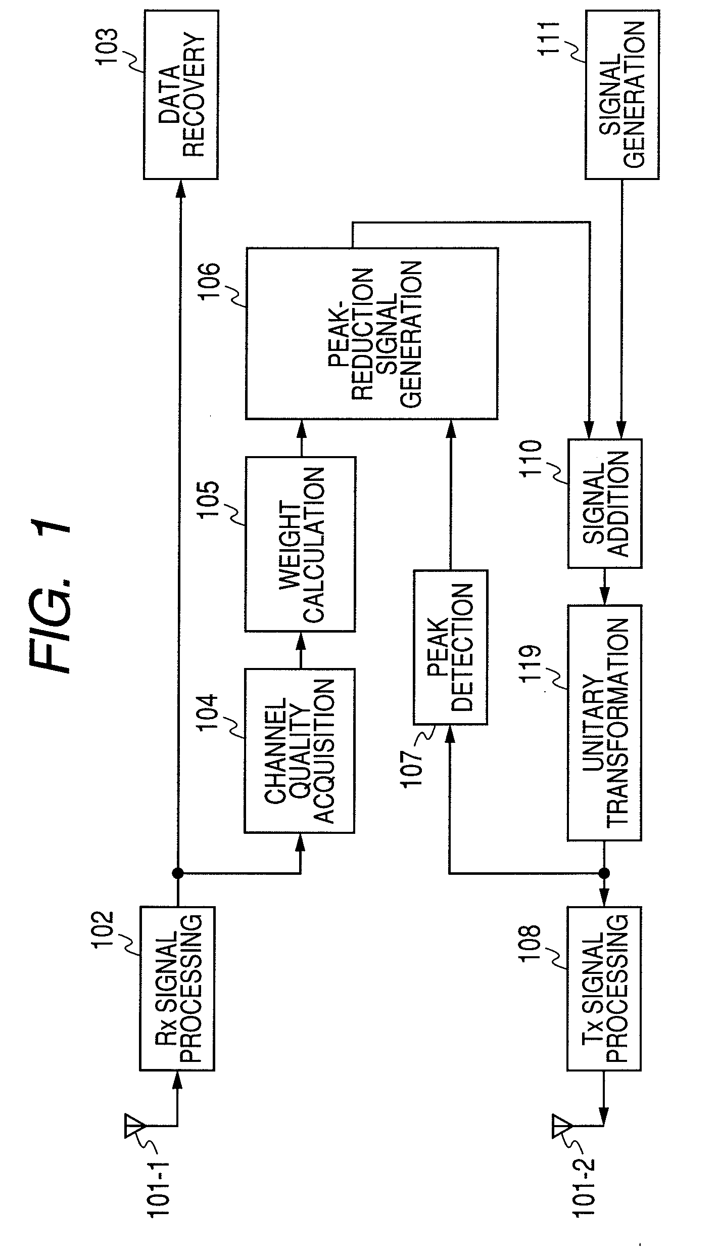
[0040]FIG. 1 shows the structure of the transceiver 114 serving as the wireless communication apparatus of this invention. This wireless communication apparatus contains a receiving antenna 101-1, a transmitting antenna 101-2, a receive (Rx) signal processing unit 102, a data recovery unit 103, a channel quality acquisition unit 104, a weight calculation unit 105, a peak suppression signal generation unit 106, a peak detection unit 107, a transmit (Tx) signal processing unit 108, a unitary transformation unit 109, a signal addition unit 110, and a signal generation unit 111.

[0041]The receiving antenna 101-1 receives the signal. The receiving antenna 101-1 need not be one unit and may include multiple units.

[0042]The receiver (hereafter Rx) signal processing unit 102 converts the received analog signal to a digital signal. The Rx signal ...

second embodiment

[0075]In this embodiment, the weight of communication modes of good communication quality is set to 0, and the weight of communication modes of bad quality is set to 1 in the weight calculation unit 105 of the first embodiment. Communication modes can for example be arrayed in the order of good communication quality (high SNR) and if the weight of the good half of the communication mode is set to 0, and the weight of the bad half of the communication modes is set to 1, then no distortion signals need be distributed to the modes in the, half with good communication quality, and equivalent distortion signals allotted to modes in the half with bad quality. This method yields the effect that calculation be easily completed.

[0076]In the description of the above example, the communication modes were distributed into modes with good communication quality and modes with bad communication quality. However, the parameters for the distribution ratio can be set as needed by the communication sy...

third embodiment

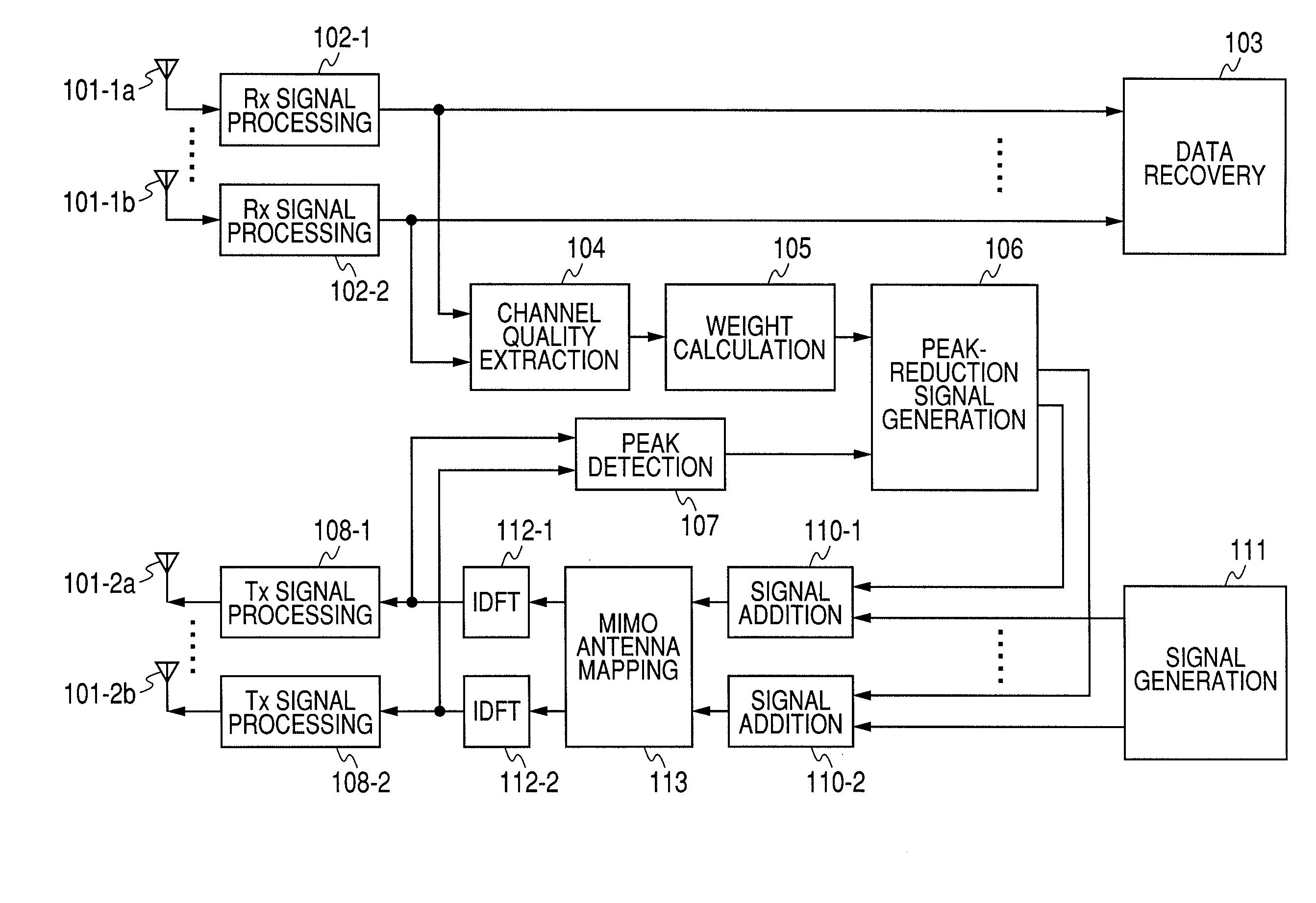
[0077]FIG. 2 shows the structure of the OFDM wireless communication apparatus of this invention. This wireless communication apparatus contains a receiving antenna 101-1, a transmitting antenna 101-2, a receive (Rx) signal processing unit 102, a data recovery unit 103, a channel quality acquisition unit 104, a weight calculation unit 105, a peak suppression signal generation unit 106, a peak detection unit 107, a transmit (Tx) signal processing unit 108, an inverse discrete Fourier transform (IDFT) unit 112, a signal addition unit 110, and a signal generation unit 111.

[0078]The receiving antenna 101-1 receives the signal. The receiving antenna 101-1 need not be one unit and may include multiple units.

[0079]The receive (hereafter Rx) signal processing unit 102 converts the received analog signal to a digital signal. The Rx signal processing unit 102 includes a filter for removing noise and interference outside the signal band from the analog data, a down converter for converting the ...


PUM


Abstract

A method for suppressing the peak-to-average power ratio (PAPR) while limiting deterioration in signal characteristics in wireless communication devices utilizing wireless communication methods (OFDM method, MIMO method) for multiplexing and sending multiple signals. A weight calculator unit sets a large weight for transmit signals whose channel quality is poor, relative to the weight of each base component based on the acquired channel quality. A peak detector unit detects the peak from the signal string after unitary conversion, and extracts a distortion component to apply for suppressing the peak. A peak suppression signal generation unit calculates the peak signal from the distortion component and weight of each base component, to add to each base component, and adds the peak suppression signal to each base component prior to unitary transformation.

Description

CLAIM OF PRIORITY[0001]The present application claims priority from Japanese patent application JP 2007-220496 filed on Aug. 28, 2007, the content of which is hereby incorporated by reference into this application.FIELD OF THE INVENTION[0002]This invention relates to a communication method and communication apparatus for wireless communication systems sending multiple signals by multiplexing such as orthogonal frequency division multiplexing (OFDM) where multiple subcarrier signals are formed as discrete Fourier transforms, and Multiple-Input Multiple-Output (MIMO) where multiple signals are superimposed or multiplexed and sent from multiple antennas.BACKGROUND OF THE INVENTION[0003]Demand for communication systems with greater capacity in recent years has focused much attention on methods such as orthogonal frequency division multiplexing (OFDM) and multiple-Input Multiple-Output (MIMO).[0004]In OFDM, multiple signals are formed as a waveform by Inverse Discrete Fourier Transform p...

Claims


Application Information

Patent Timeline
IPC IPC(8): H04L27/28H04L25/49
CPCH04L5/0023H04L5/006H04L27/2647H04L27/2623H04L27/2626H04L25/0224
Inventor HAYASE, SHIGENORIYANO, TAKASHISHIDA, MASAAKIYAMAMOTO, KEISUKEJIA, YUNJIAN
Owner HITACHI LTD
Why Eureka
Try Eureka