Measurement apparatus, exposure apparatus, and device fabrication method

Inactive Publication Date: 2009-03-12
CANON KK
View PDF10 Cites 19 Cited by
  • Summary
  • Abstract
  • Description
  • Claims
  • Application Information

AI Technical Summary

Benefits of technology

[0016]The present invention provides a measurement apparatus which can measure both the non-polarization aberration and the polarization aberration (the retardation and azimuth of birefrin

Problems solved by technology

However, even when the polarization state of the exposure light is controlled to a desired one by the illumination optical system, the polarization state of the exposure light in the projection optical system often changes due to, for example, the holding of a lens, the deformation of a lens due to heat, the use of a birefringent glass material, or the reflection of the exposure light by a mirror.
Unfortunately, these prior arts cannot simultaneously measure the non-polarization aberration and the polarization aberration (the retardation and azimuth of birefringence), while the projection optical system is mounted in the exposure apparatus, with high accuracy in a short period of time.
Still worse, it is difficult to apply such an interferometer to measurement on the exposure apparatus because the exposure light has a very short coherence length.
However, the use of only the two orthogonal linearly polarized light beams is insufficient to precisely measure the polarization aberration of the projection optical system.
This may make it impossible to measure the optical characteristics with high accuracy

Method used


Image

  • Measurement apparatus, exposure apparatus, and device fabrication method
  • Measurement apparatus, exposure apparatus, and device fabrication method
  • Measurement apparatus, exposure apparatus, and device fabrication method

Examples


first embodiment

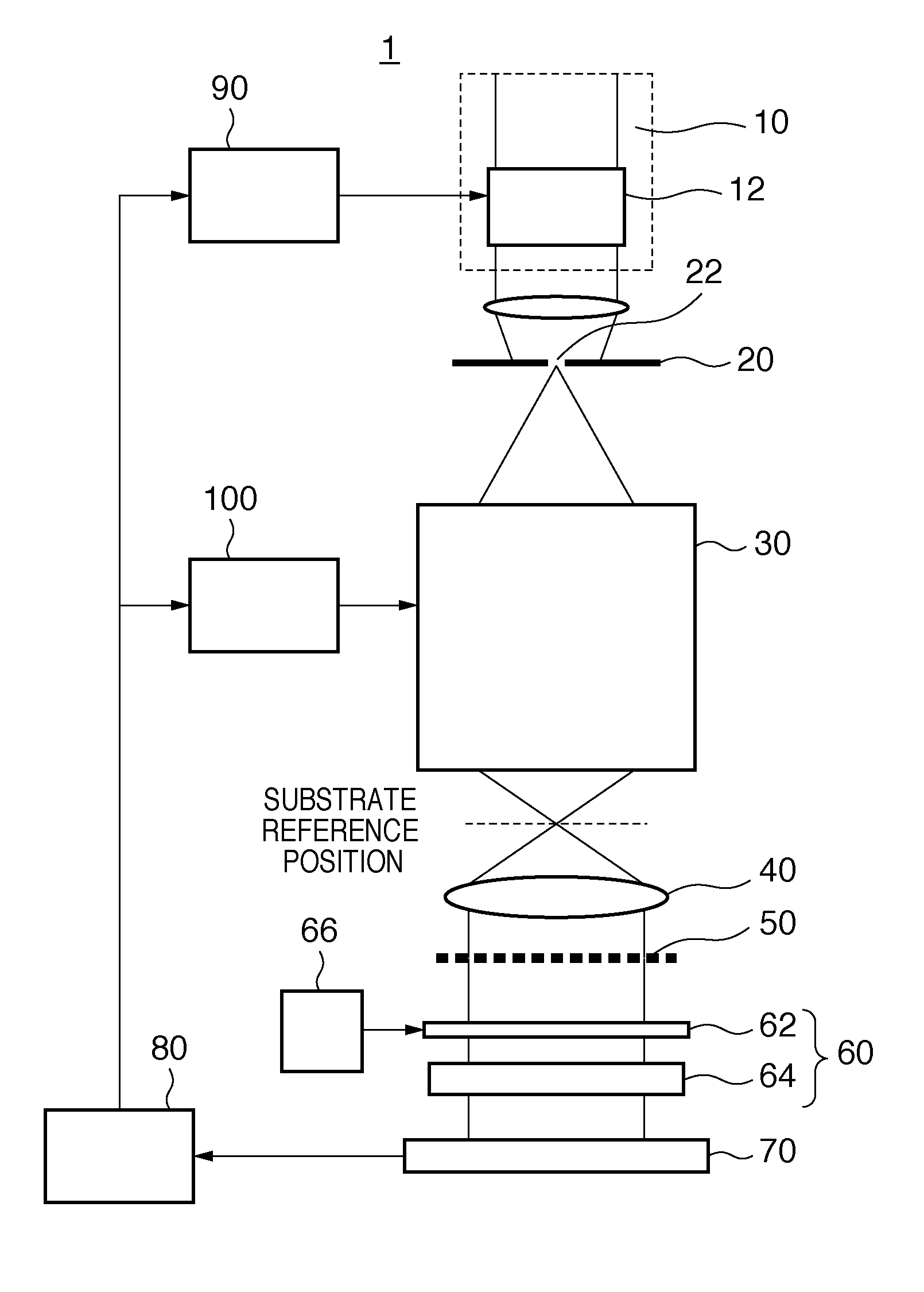
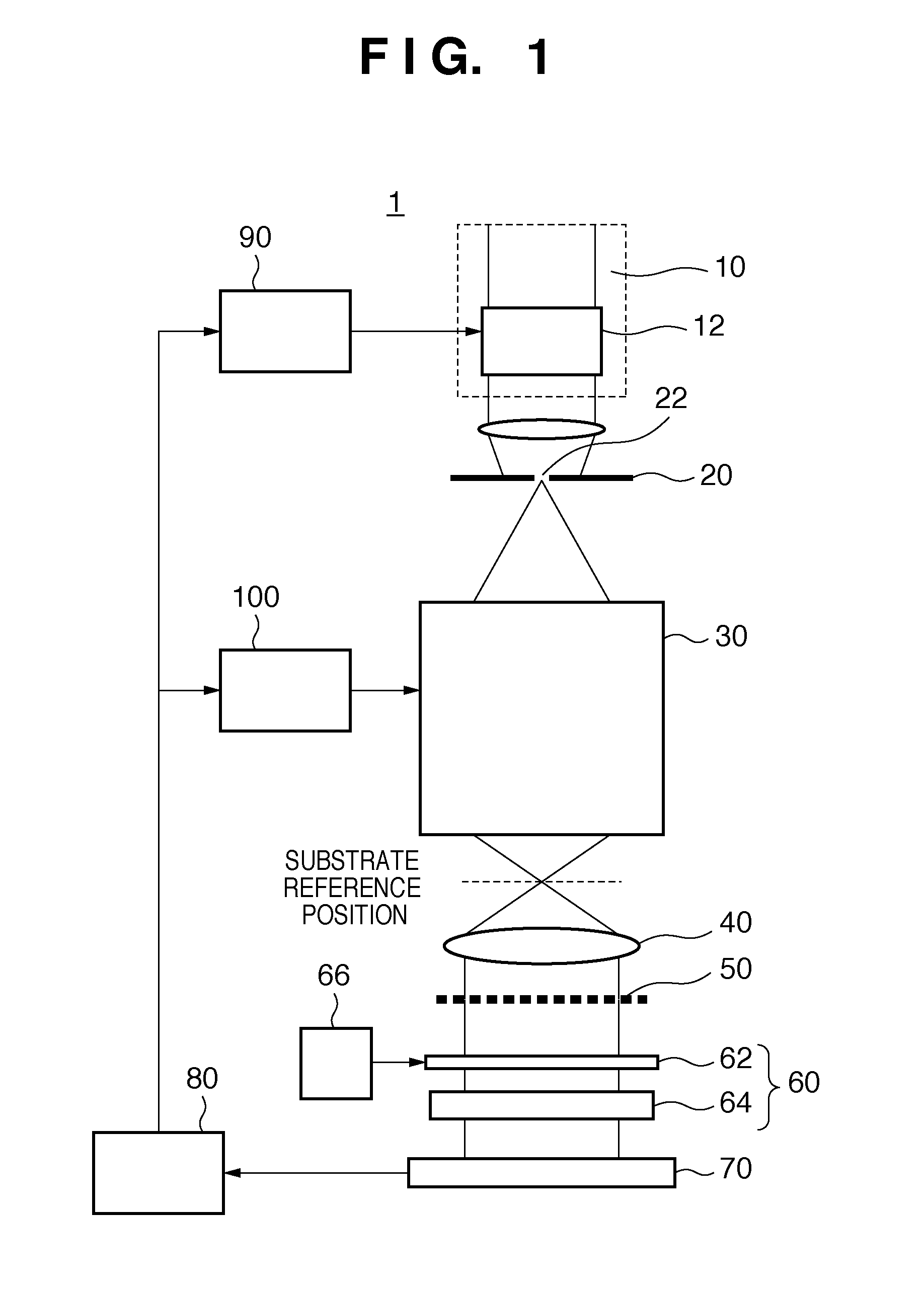
[0034]FIG. 1 is a schematic block diagram showing the arrangement of an exposure apparatus 1 according to the first embodiment of the present invention. An example of the exposure apparatus 1 is a projection exposure apparatus which transfers the pattern of a reticle onto a wafer (substrate) by exposure using the step & scan scheme. However, the exposure apparatus 1 can adopt the step & repeat scheme or another exposure scheme.

[0035]The exposure apparatus 1 illuminates a reticle with light from a light source and projects (transfers) by exposure the pattern of a reticle onto a wafer, which is set at a substrate reference position, while scanning them. The substrate reference position herein is the focus position of a projection optical system 30 (i.e., the image plane of the projection optical system 30). The exposure apparatus 1 includes an illumination apparatus including a light source and an illumination optical system 10 for illuminating the reticle with light from the light so...

second embodiment

[0085]FIG. 6 is a schematic block diagram showing the arrangement of an exposure apparatus 1A according to the second embodiment of the present invention. Although the exposure apparatus 1A has an arrangement and functions similar to those of the exposure apparatus 1 according to the first embodiment, a measurement apparatus provided to the exposure apparatus 1A has an arrangement different from that of the measurement apparatus provided to the exposure apparatus 1. The measurement apparatus measures the non-polarization aberration and polarization aberration of a projection optical system 30 as its optical characteristics, and constitutes a point diffraction interferometer (PDI). The point diffraction interferometer is a common path interferometer, which is less likely to come under the influence of vibration because of its simple optical path and arrangement. Note that an illumination system control unit 90 and projection system control unit 100 are not illustrated in FIG. 6.

[0086...

third embodiment

[0101]FIG. 9 is a schematic block diagram showing the arrangement of an exposure apparatus 1B according to the third embodiment of the present invention. Although the exposure apparatus 1B has an arrangement and functions similar to those of the exposure apparatus 1 according to the first embodiment, a measurement apparatus provided to the exposure apparatus 1B has an arrangement different from that of the measurement apparatus provided to the exposure apparatus 1. The measurement apparatus includes a wavefront splitting unit 50, second polarization control unit 60 (phase plate 62 and polarizer 64), and detection unit 70 on the side of the object plane of a projection optical system 30 (i.e., on the reticle side). In other words, the measurement apparatus of the exposure apparatus 1B constitutes a shearing interferometer on the side of the object plane of the projection optical system 30, and measures the non-polarization aberration and polarization aberration of the projection opti...


PUM


Abstract

The present invention provides a measurement apparatus comprising a first polarization control unit configured to control a polarization state of light which enters an optical system to be measured to at least two different polarization states, a wavefront splitting unit which is inserted between the first polarization control unit and the optical system, a second polarization control unit which is inserted between the optical system and an image sensor, includes a phase plate, and is configured to control the polarization state of the light, and a processing unit configured to calculate the optical characteristics of the optical system, based on a plurality of interference patterns sequentially sensed by the image sensor by rotating the phase plate.

Description

BACKGROUND OF THE INVENTION[0001]1. Field of the Invention[0002]The present invention relates to a measurement apparatus, an exposure apparatus, and a device fabrication method.[0003]2. Description of the Related Art[0004]An exposure apparatus has conventionally been employed to fabricate micropatterned semiconductor devices such as a semiconductor memory and logic circuit by using photolithography. The exposure apparatus projects and transfers a circuit pattern formed on a reticle (mask) onto a substrate such as a wafer by a projection optical system.[0005]A minimum line width (resolution) that the exposure apparatus can transfer is proportional to the exposure light wavelength and is inversely proportional to the numerical aperture (NA) of the projection optical system. Along with the recent demand for increasing the packing density and the degree of integration of semiconductor devices, the exposure apparatus is required to attain a higher resolution. To meet this demand, the exp...

Claims


Application Information

Patent Timeline
IPC IPC(8): G03B27/72G01B9/02
CPCG03F7/70566G03B27/72G01M11/0242G03F7/20
Inventor OHSAKI, YUMIKOTAKEUCHI, SEIJI
Owner CANON KK
Why Eureka
Try Eureka