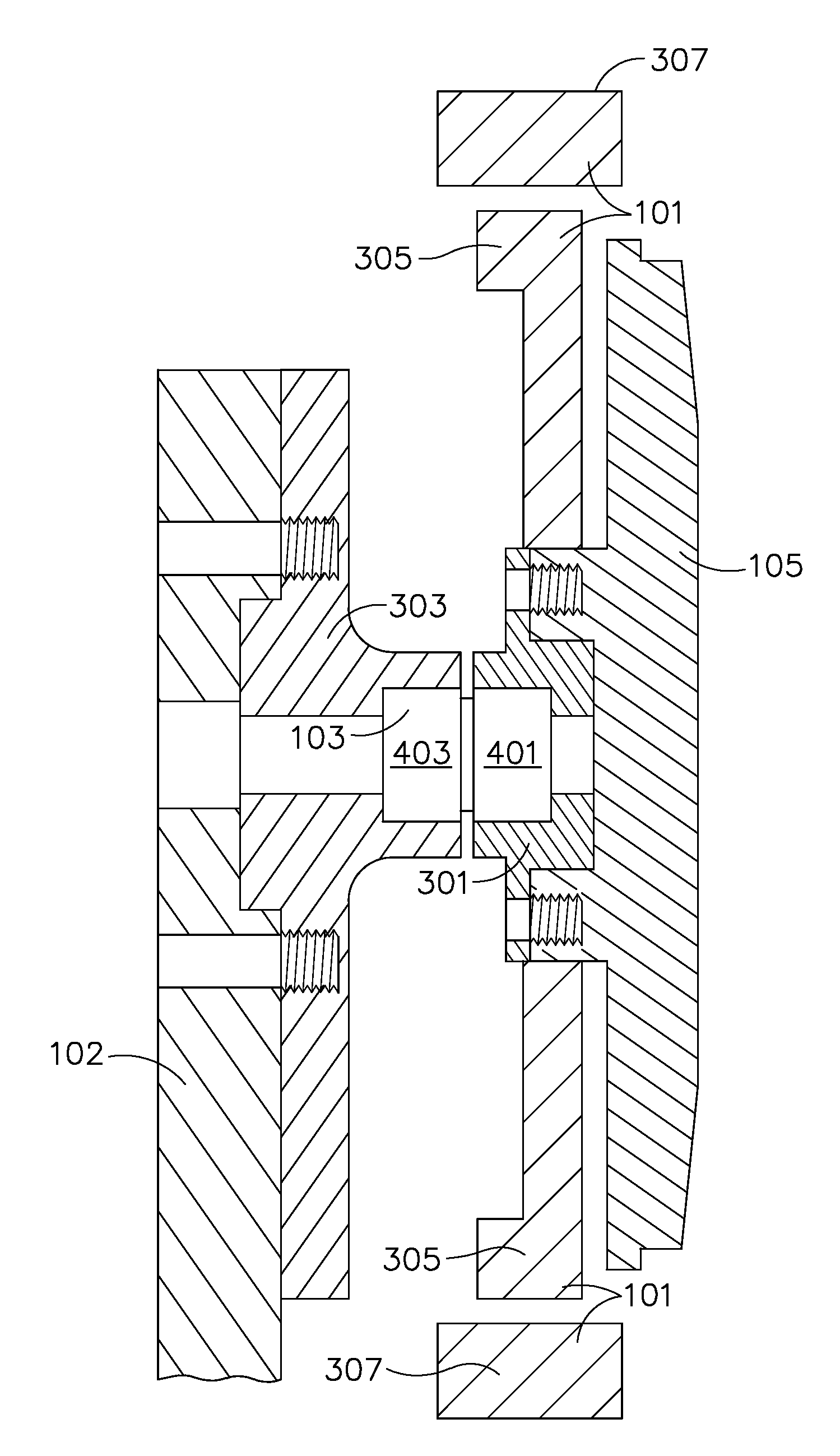
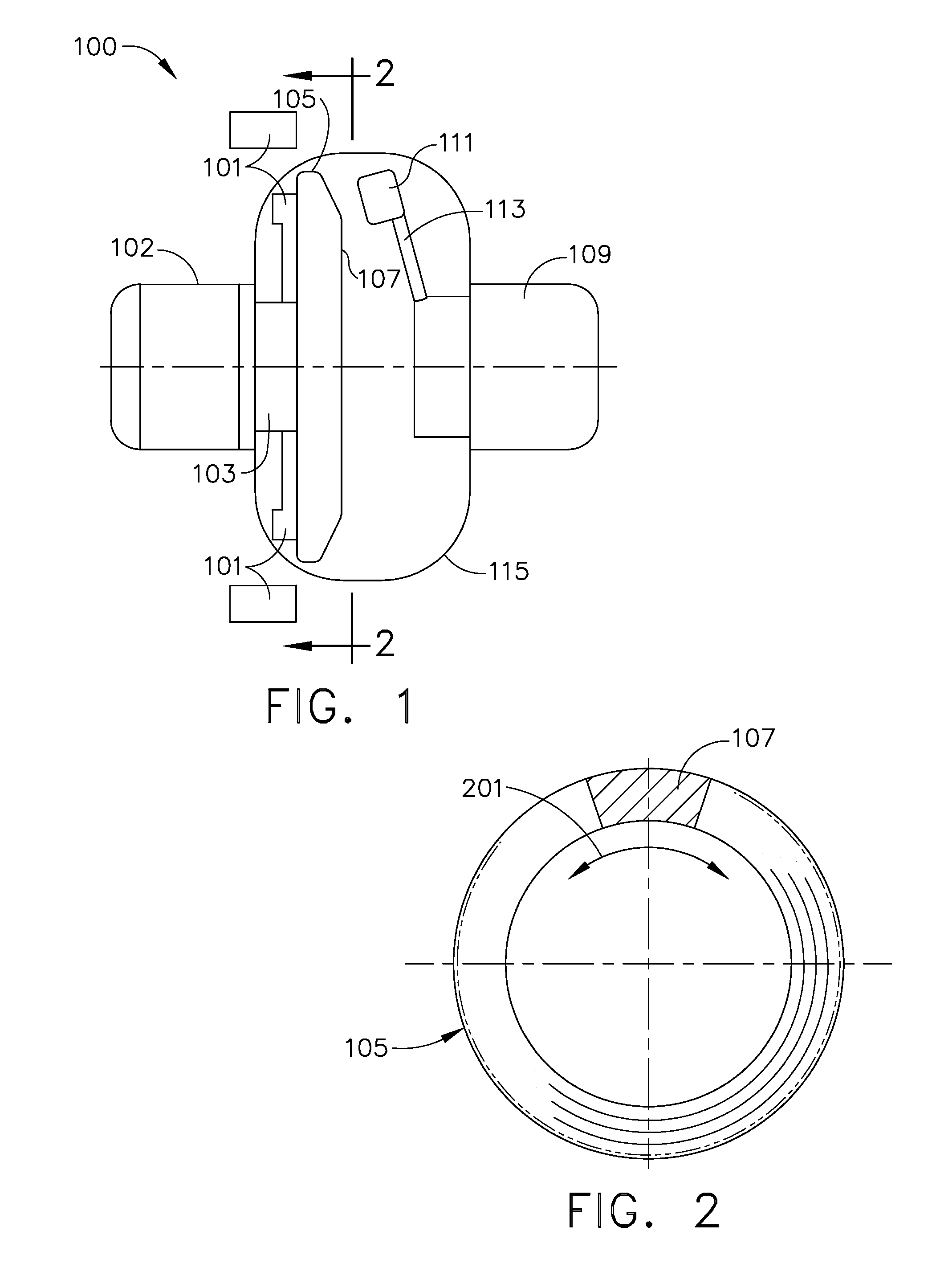
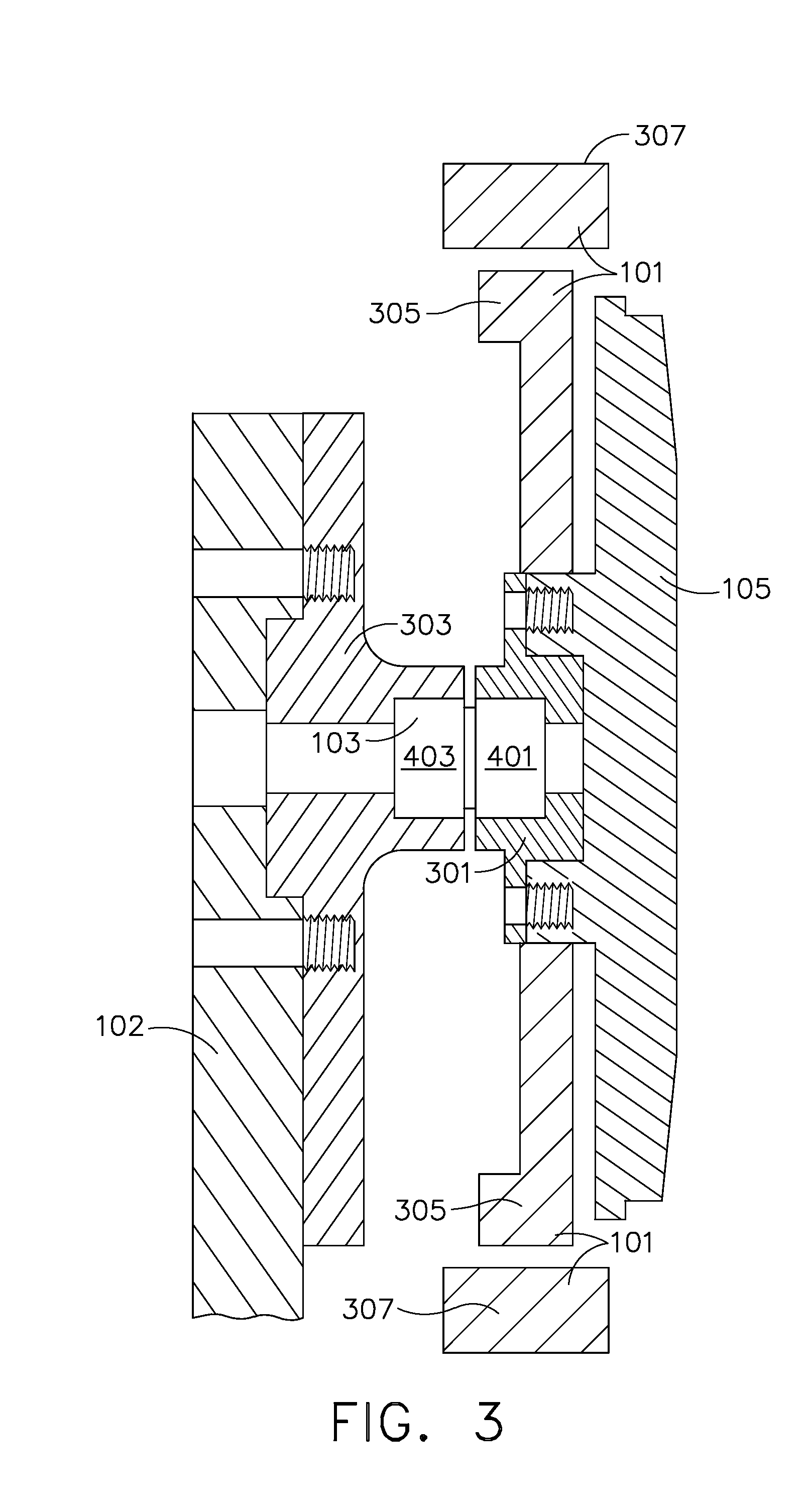
High flux x-ray target and assembly

a high-flux, x-ray tube technology, applied in the direction of x-ray tube electrodes, electrical devices, electric discharge tubes, etc., can solve the problems of deterioration and breakdown of the target structure, relatively low life, and major heating problems, so as to reduce the temperature gradient

Inactive Publication Date: 2009-03-19
BAKER HUGHES INC
View PDF14 Cites 8 Cited by
  • Summary
  • Abstract
  • Description
  • Claims
  • Application Information

AI Technical Summary

Benefits of technology

[0014]Embodiments of the present disclosure also allow the distribution of heat over a larger area of the anode target, through the oscillating motion, which reduces th...

Problems solved by technology

In addition, the high velocity beam of electrons impinging the target surface generates extremely high and localized temperatures in the target structure accompanied by high internal stresses leading to deterioration and breakdown of the target structure.
Heating remains a major problem in X-ray anode target structures.
Traditional x-ray target bearings are solid lubricated, which have relatively low life.
Stationary targets do not have this li...

Method used


Image

  • High flux x-ray target and assembly
  • High flux x-ray target and assembly
  • High flux x-ray target and assembly

Examples


examples

[0037]An example finite element analysis comparing a stationary target to a oscillating target with + / −9.5° degree oscillation at 10 Hz on a 78 mm radius arc shows an entitlement of 2.3× power increase while maintaining thermal limits of track surface temperature <2400° C. and copper temperatures of <300° C. One skilled in the art would note that the power increase is gated by the optimization of the track oscillation angle, oscillation frequency and focal spot path radii. In addition, the power increase includes varied system size, cost and expected life span. The oscillatory motion introduces transient temperature fields on the surface of the anode target that will have a peak dwell time of the focal beam at the end of the oscillation path. The ends of the oscillation path determine the thermal limit of the track surface.


PUM


Abstract

An X-ray tube anode assembly, an X-ray tube assembly and a method for heat management to an X-ray assembly having a movable X-ray target having a target surface. The anode assembly includes a drive member arranged and disposed to provide oscillatory motion to the target assembly and a target surface that is configured to remain at a substantially fixed distance from a cathode assembly during oscillatory motion.

Description

FIELD OF THE INVENTION[0001]This disclosure relates to an X-ray tube anode target assembly and, more particularly, to configuration and structures for controlling heat dissipation and structural loads for an X-ray tube anode target assembly.BACKGROUND[0002]Ordinarily an X-ray beam-generating device referred to as an X-ray tube comprises dual electrodes of an electrical circuit in an evacuated chamber or tube. One of the electrodes is electron emitter cathode which is positioned in the tube in spaced relationship to a target anode. Upon energization of the electrical circuit generates a stream or beam of electrons directed towards the target anode. This acceleration is generated from a high voltage differential between the anode and cathode that may range from 60-450 kV, which is a function of the imaging application. The electron stream is appropriately focused as a thin beam of very high velocity electrons striking the target anode surface. The anode surface ordinarily comprises a ...

Claims


Application Information

Patent Timeline
IPC IPC(8): H01J35/02
CPCH01J35/28
Inventor VADARI, HARITHFRONTERA, MARKSRIDHAR, MANDYAMVENUGOPAL, MANOHARANMISHRA, DEBASISHSEBASTIAN, SAVIO
Owner BAKER HUGHES INC
Why Eureka
Try Eureka