
Substrates having through-hole vias and method of making same

a technology of through-hole vias and substrates, applied in the field of sensors, can solve the problems of relatively insensitive electronic sensors and poor performance of acoustic sensors in aqueous environments, and achieve the effects of reducing costs, good electrical interfaces, and more accurate and sensitive analysis

Inactive Publication Date: 2009-03-19
BIOSCALE
View PDF36 Cites 7 Cited by
  • Summary
  • Abstract
  • Description
  • Claims
  • Application Information

AI Technical Summary

Benefits of technology

The patent describes a sensor that can be used in various applications and is tolerant to changes in environmental or system temperature. The sensor is made up of microfabricated resonant sensors that can monitor changes in surface properties of a sensor membrane caused by a binding event. The sensor can be used as an array of sensors, which can be cost-effective and efficient in analyzing biologic samples. The sensor is particularly useful in biologic applications where aqueous environments are the norm. The sensor can detect changes in force, pressure, and mass on the surface of a sensor membrane using a binding partner specific for the analyte or target. The sensor is made up of a tetramer composed of two identical pairs of polypeptide chains. The sensor is immunoglobulin-based and can be used as an analyte or a binding partner. The sensor is advantageous in biologic applications where aqueous environments are the norm.

Problems solved by technology

Acoustic sensors do not perform well in aqueous environments.
Electronic sensors remain relatively insensitive.

Method used


Image

  • Substrates having through-hole vias and method of making same
  • Substrates having through-hole vias and method of making same
  • Substrates having through-hole vias and method of making same

Examples


example 1

Use of a Resonant Sensor as a Density Sensor

[0210]As described above, the device detects changes in density conferred by concentration of biological molecules in the space above the sensor. Biological molecules such as protein (density 1.3) DNA (density 1.5) and RNA (density 1.7) are substantially higher than that of water (density 1.0). and substantially higher than those of cells (density 1.05-1.09). However, when present in a monolayer, this altered density is barely seen because it only creates a very thin layer of altered density and the net density in the sphere is not substantially changed. The sensitivity of detection of the devices described herein may be amplified by creating a 3 dimensional region of binding (using a hydrogel) which extends farther out into the hemisphere of water interrogated by the resonant membrane. The hydrogel-bonded resonant sensor is prepared as described in U.S. patent application Ser. No. 10 / 306,506 (Atty Docket No. 035300-0502, filed Nov. 26, 20...

example 2

Use of a Resonant Sensor to Map Expression of Proteins

[0212]Antibodies immobilized to the resonant sensor may be used to map the expression of cellular proteins, much as nucleic acid “chips” currently are used to map the expression of cellular RNAs. In this case, an unlabeled protein extract is applied to a resonant sensor array containing antibodies of interest embedded into a hydrogel. The hydrogel-bonded resonant sensor is prepared as described in U.S. patent application Ser. No. 10 / 306,506 (Atty. Docket No. 035300-0502, filed Nov. 26, 2002). These antibodies may detect all forms of the protein, or may be designed to detect specific conformers (e.g. phosphorylated forms). Binding of the protein confers a density shift, which may then be augmented by addition of a mass enhancement reagent. This reagent could be used to distinguish conformational subtypes (e.g. a phosphorylated form as above) or may be a natural dimerization partner. Thus allowing determinations of both structure (...

example 3

Use of a Resonant Sensor to Assess Enzyme Activities

[0213]An array of enzyme substrates is produced by embedding the substrates in a hydrogel. The hydrogel-bonded resonant sensor is prepared as described in U.S. patent application Ser. No. 10 / 306,506 (Atty Docket No. 035300-0502, filed Nov. 26, 2002). The resulting array is contacted with one or more enzymes of interest (e.g., kinases, hydrolases, esterases, etc.) and the resulting modification to each substrate is detected by a mass conferring specificity agent (e.g. a phosphor-tyrosine specific antibody or a phosphor specific chelate. Changes in mass or density within the sensed volume above each sensor in the array are monitored by monitoring resonant frequency of the sensor membrane.

[0214]An enzymatic activity sensor as described is used to detect changes in mass conferred by enzymatic addition of mass to a substrate. In the case of DNA assays, the rolling circle, anchored SDA, anchored PCR and anchored NASBA reactions may be mo...


PUM

PropertyMeasurementUnit
lengthaaaaaaaaaa
radiusaaaaaaaaaa
radiusaaaaaaaaaa

Abstract

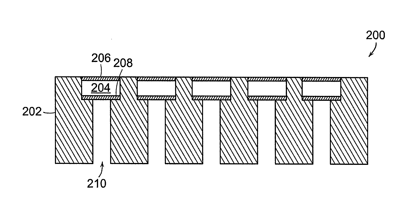
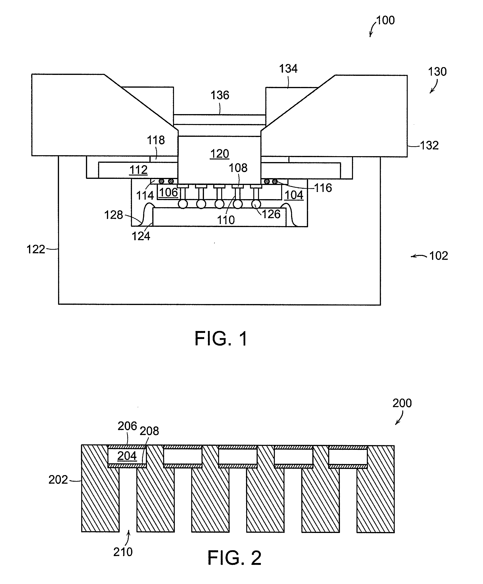
A sensor assembly for sensors such as microfabricated resonant sensors is disclosed. The disclosed assembly provides improved performance of the sensors by providing a thermally insensitive environment and short pathways for signals to travel to processing components. Further, the assembly provide modular construction for the sensors and housing modules, thereby allowing replacement of the sensors at a lower cost. The assembly includes a sensor module including a sensor formed on a conductive substrate with a cavity formed on one surface. The substrate has conductive vias extending from the cavity to a second surface of the substrate. A housing assembly accommodates the sensor and includes a rigid housing, preferably made from a ceramic. An electronic component, such as an amplifier, is mounted on the rigid housing. The electronic component electrically engages the vias substantially at the second surface of the substrate. The electronic component receive signals from the sensor through the vias. The signals are then processed through an amplifier and a digital signal processor using a modified periodogram.

Description

[0001]This application is a continuation of U.S. patent application Ser. No. 10 / 392,446, entitled SUBSTRATES HAVING THROUGH-HOLE VIAS AND METHOD OF MAKING SAME, filed Mar. 17, 2003; which is a continuation in part of U.S. patent application Ser. No. 09 / 845,521, entitled MICROFABRICATED ULTRASOUND ARRAY FOR USE AS RESONANT SENSORS, filed Apr. 26, 2001; which claims priority to U.S. Provisional Patent Application No. 60 / 233,961, filed Sep. 20, 2000; and of International Application No. PCT / US01 / 29487, entitled MICROFABRICATED ULTRASOUND ARRAY FOR USE AS RESONANT SENSORS, filed Sep. 20, 2001, each of which is hereby incorporated by reference in its entirety, including all tables, figures and claims.FIELD OF THE INVENTION[0002]The present invention relates to sensors for monitoring a change in force as applied to a surface membrane or a change in the surface properties of the sensor membrane. More particularly, the invention relates to a microfabricated mechanical resonant sensor and a ...

Claims


Application Information

Patent Timeline
Patent Type & Authority Applications(United States)
IPC IPC(8): B05D5/12B06B1/02G01N33/483B81B3/00G01N5/02G01N29/02G01N29/22G01N33/566
CPCB06B1/0292Y10T29/53052G01N29/022G01N29/222G01N29/223G01N2291/014G01N2291/0255G01N2291/0256G01N2291/02818G01N2291/0423G01N2291/0427G01N2291/106Y10T29/49128Y10T29/4913Y10T29/49169Y10T29/49126G01N29/02
Inventor BELLEW, COLBYCOLLINS, BOYCE E.LIU, KELVIN
Owner BIOSCALE
Learn More