Inkjet printing of materials for use in fuel cells

Inactive Publication Date: 2009-03-19
THE RGT OF THE UNIV OF MICHIGAN
View PDF6 Cites 14 Cited by
  • Summary
  • Abstract
  • Description
  • Claims
  • Application Information

AI Technical Summary

Benefits of technology

[0017]For fuel cell applications, the inventive IJP technology resolves many of the problems associated with previous methods of catalyst deposition by allowing a uniform distribution of catalyst material onto the surface of the GDL (CCE) or electrolyte CCM (i.e. CCE or CCM catalyst coated electrodes or membranes). With a fixed nozzle volume, each printing delivers precise picoliter control of deposition, which is useful for creating membrane electrode assemblies (MEA) with ultra low (e.g., <0.05 mg Pt cm−2) loadings.
[0018]Inkjet printing (IJP) has thus been demonstrated as a catalyst application method for PEMFCs. The resulting anodes gave comparable, if not better performance than those fabricated using conventional screen printing or hand painting methods. The high precision of IJP allows for controlled catalyst deposition, especially for ultra low platinum (Pt) loadings. These low loadings, which are not easily attained using conventional methods, give some of the highest Pt utilizations reported in the prior art.

Problems solved by technology

First, the uniformity of catalyst deposited on the electrode is not easily controlled and can vary depending on the person depositing the catalyst material.
Second, these processes can be time consuming, requiring iterations of painting, drying, and massing to achieve the desired loading of catalyst. Iterations of the weighing and painting steps, in addition to solvent evaporation or changes in mass uptake of the brush can contribute to poor reproducibility. Spray painting overcomes many of the problems associated with brush painting and allows for a more uniform distribution of catalyst material. It also opens the doors to automation for large scale production; however, a considerable amount of catalyst is often wasted in the feed lines due to periodic clogging which could increase the cost of production.
However, existing ink deposition methods such as spray painting or screen printing are not well suited for ultra low (−2) loadings.
One of the obstacles preventing the commercialization of fuel cells is the utilization of noble metals, most often platinum (Pt) or platinum-based alloys, to catalyze the oxidation and reduction reactions.
While this method could allow for large scale production, the expenditure is still substantial due to costs associated with clean rooms, Pt targets, and ultra high vacuum equipment.
In addition, the Pt deposited is often unsupported and the electrolyte cannot be deposited simultaneously with the Pt limiting the catalyst layer to only two dimensions.

Method used


Image

  • Inkjet printing of materials for use in fuel cells
  • Inkjet printing of materials for use in fuel cells
  • Inkjet printing of materials for use in fuel cells

Examples


Embodiment Construction

)

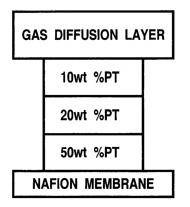
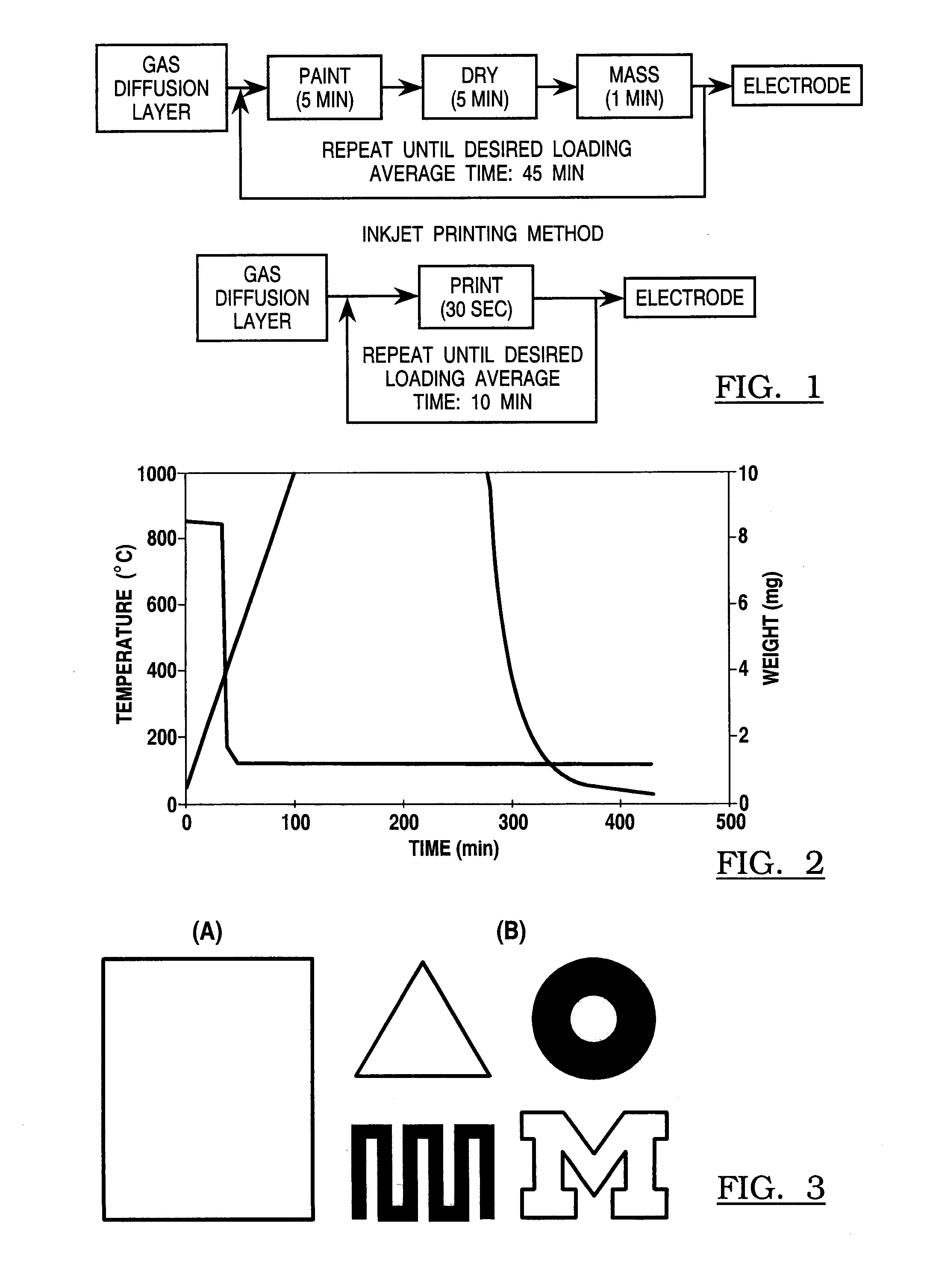
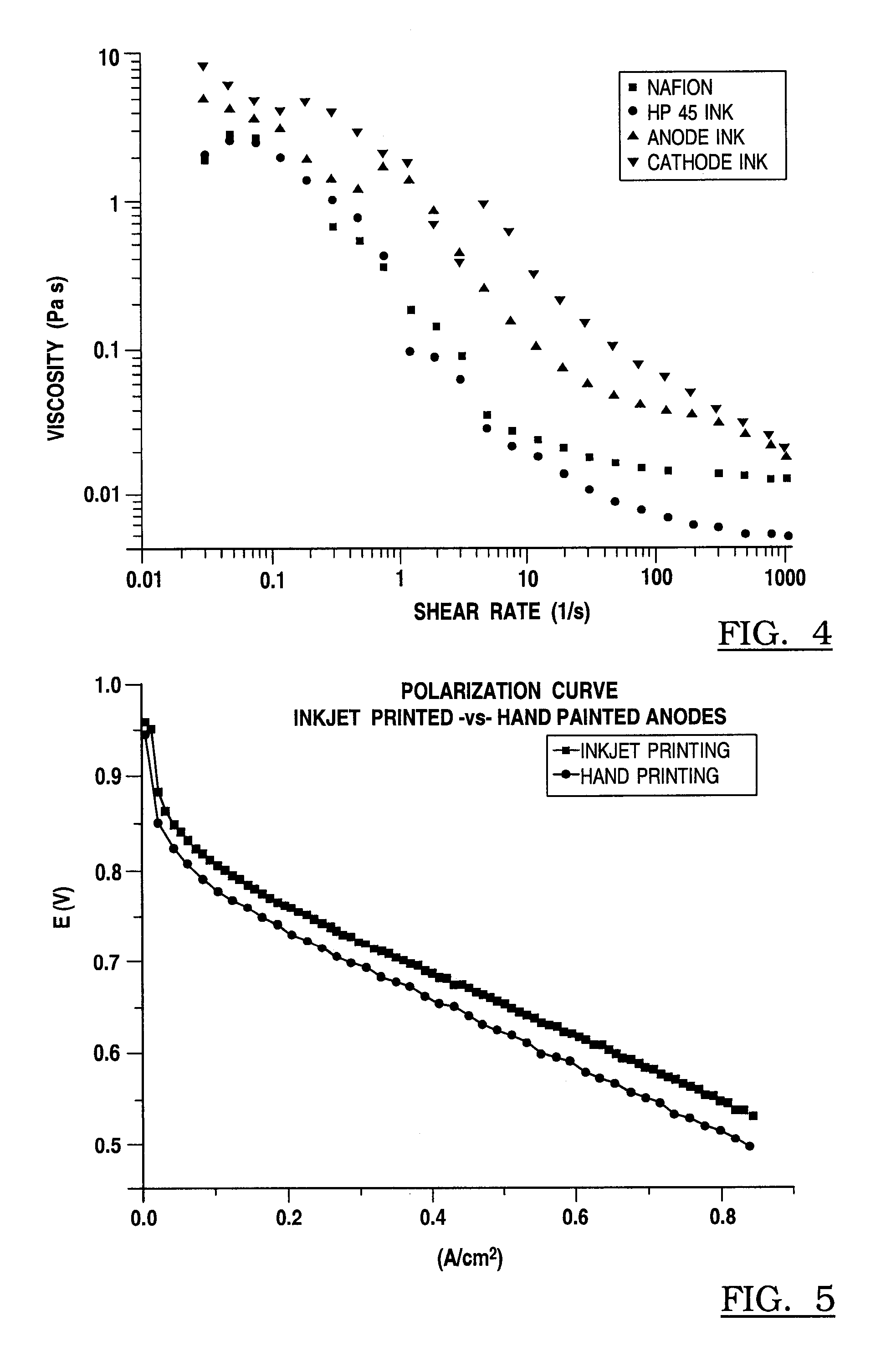
[0029]Conventional inkjet printing technology can reproducibly dispense small droplets of fluid onto a desired location upon a substrate. The present invention discloses a material flowing through a nozzle in an inkjet cartridge, the material including three main components: (1) a catalyst (for example, carbon powder); (2) a metal (such as platinum powder); and (3) a polyelectrolyte in solution form (e.g. Nafion® 117). These components are carried in a liquid solvent which ultimately disperses after the effluent is deposited on a substrate. As used herein, the term “catalyst ink material” is used to demote the effluent from the inkjet printer.

[0030]The present invention comprehends such substrates as gas diffusion layers, (e.g. carbon cloth or carbon paper), and a solid polyelectrolyte, such as but not limited to Nafion® 117.

[0031]What results is a deposit of a catalyst material that is delivered with picoliter precision that can be used, for example, to create membrane electrode a...


PUM


Abstract

A method of using inkjet printing (IJP) to deposit catalyst materials onto substrates such as gas diffusion layers (GDLs) that in one application are made into membrane electrode assemblies (MEAs) for polymer electrolyte fuel cells (PEMFC). The inventive IJP method can deposit smaller volumes of water-based catalyst ink solutions with picoliter precision. By optimizing the dispersion of the ink solution, this technique can be used with catalysts supported on different specimens of carbon black.

Description

CROSS-REFERENCE TO RELATED APPLICATIONS[0001]This application claims the benefit of U.S. provisional application Ser. No. 60 / 993,664 filed Sep. 13, 2007, which is incorporated herein by reference.BACKGROUND OF THE INVENTION[0002]1. Field of the Invention[0003]The invention relates to the printing of catalyst material intended primarily but not exclusively for use in fuel cells by inkjet printing methods.[0004]2. Background Art[0005]Polymer electrolyte membrane fuel cells (PEMFC's) are rapidly gaining attention as alternatives to current power sources due to their high efficiencies and ability to operate without greenhouse gas emissions. It is known that carbon supported platinum nanoparticles (Pt / C) as well as various platinum alloys on carbon are sometimes used as electrocatalysts in polymer electrolyte membrane fuel cells (PEMFC). They catalyze the anodic oxidation of oxygen and the cathodic reduction of oxygen. It is also known that the type of the support can influence the activ...

Claims


Application Information

Patent Timeline
IPC IPC(8): B05D5/12B05C5/02
CPCC09D11/30H01G9/0036H01M4/8642H01M4/8657H01M4/8807Y02E60/521H01M4/8832H01M4/926H01M8/1004H01M2008/1095H01M4/881Y02E60/50
Inventor TAYLOR, ANDRE D.
Owner THE RGT OF THE UNIV OF MICHIGAN
Why Eureka
Try Eureka