Disposable Stereoscopic Endoscope System

a stereoscopic endoscope and system technology, applied in the field of endoscopes, can solve the problems of limited performance of endoscopes based on fiber cables, limited application potential, optical attenuation, etc., and achieve the effect of low cos

Inactive Publication Date: 2009-03-19
SU WEI +1
View PDF11 Cites 123 Cited by
  • Summary
  • Abstract
  • Description
  • Claims
  • Application Information

AI Technical Summary

Benefits of technology

[0014]In this invention, the word “disposable endoscope” means an endoscope that is relatively compact a

Problems solved by technology

Due to the fixed positions of the relay lenses, endoscopes can only be made with a rigid shank, limiting its potential applications.
However, the inherent low resolution and high optical attenuation resulting from limitation of the optical fiber has limited the performance of endoscopes based on fiber cables.
The shortcomings of repeated use include the risk of potential cross contamination, high cost of a sustainable design, tear and wear in function, and increased personnel cost for maintenance.
However, the cost of optics, especially that of the image transmission optics and electronic imaging sensors have so far kept the cost high even for endoscopes designed as disposables (U.S. Pat. No. 7,230,756 B2).
Besides, the size of the imaging electronics prevents its placement close to the imaging optics and as a consequence the design still relies on traditional relay optics for image transmission.
Today most endoscopes are not designed and manufactured to generate stereoscopic images.
Such a spatial division based configuration also result in a larger dimension of the endoscope, and hence is unlikely to meet the requirement of minimally invasive surgeries.
Due to the higher

Method used


Image

  • Disposable Stereoscopic Endoscope System
  • Disposable Stereoscopic Endoscope System
  • Disposable Stereoscopic Endoscope System

Examples


Embodiment Construction

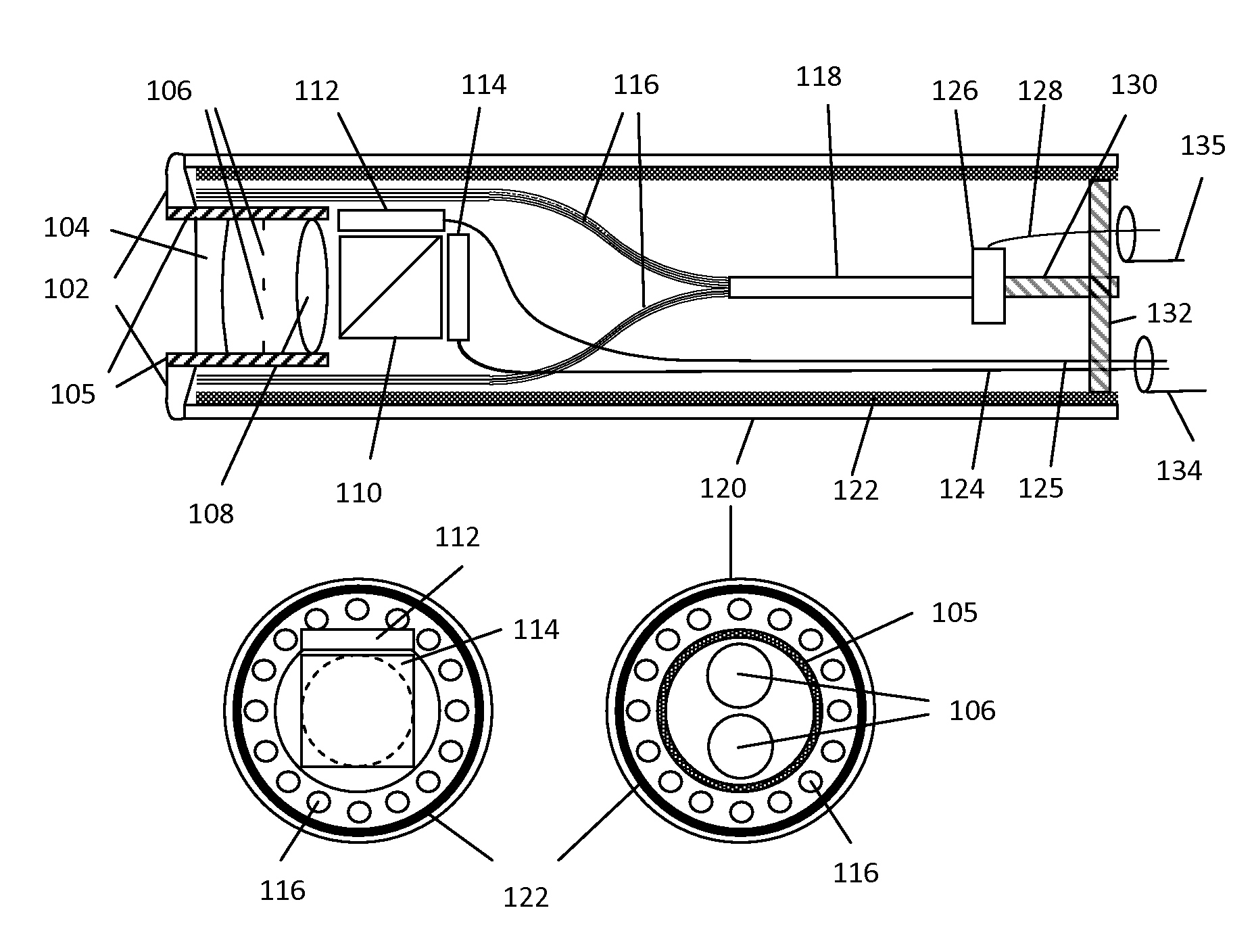
[0032]A novel simultaneous stereoscopic endoscope system based on solid state lighting is proposed. One unique feature of the present invention is the compact design of stereoscopic imaging and lighting within a disposable housing such that only electrical signal connection is required between the disposable part and the rest of the endoscope system for transmitting power, imaging and control signals. In particular, a miniature low cost digital imaging unit is placed directly at the distal end of the endoscope, which eliminates the need for a relay optical system. The new optical design makes it possible to miniaturize the imaging unit to the size similar to traditional optical endoscopes.

[0033]FIG. 1 shows a section view of the disposable imaging and lighting unit of the presently disclosed stereoscopic endoscope. In terms of imaging optics, two optical modules such as the lenses 104 and 108 are used to form two images of an object onto two electronic imaging sensors 112 and 114. T...


PUM


Abstract

A disposable simultaneous stereo endoscope system is disclosed. The disposable endoscope does not include image relay. Instead, two electronic imaging sensors and solid illumination lighting are arranged inside the endoscope. A demultiplexing beam splitter is used for splitting the two imaging light beams to the two imaging devices. A wedged multi-facet illumination window is used to create an illumination field that is larger than the field of view of the imaging optics. An electrically conductive heat sink is engaged for dissipating the heat generated by the solid light source and also for shielding end side of the endoscope. The disposable endoscope is shielded from electromagnetic interferences. A repeater unit is used to electrically connect the disposable endoscope with a remote receiver and to increase the data transfer rate. An electrical isolation means is provided between the endoscope and an image processing and power conditioning unit to protect the endoscope against electric shock.

Description

CROSS REFERENCE TO RELATED APPLICATIONS[0001]This application claims the benefit of provisional patent application Ser. No 60 / 993,858, filed Sep. 17, 2007 by the present inventors.[0002]This application is related to a co-pending U.S. patent application entitled “Compact Stereoscopic Endoscopes” which is incorporated herein by reference.US Patents[0003]U.S. Pat. No. 5,222,477[0004]U.S. Pat. No. 6,720,988[0005]U.S. Pat. No. 6,976,956[0006]U.S. Pat. No. 7,230,756FIELD OF THE INVENTION[0007]The present invention generally relates to endoscopes and in particular, to the design of a stereoscopic endoscopes system for medical procedures and industrial applications.BACKGROUND OF THE INVENTION[0008]An endoscope is an imaging device capable of transmitting image from its tip (or distal end) through its long, slim shank to an imaging sensor so that a live image can be displayed on an electronic monitor at a distance. An endoscopic system often consists of four major parts: a miniature imaging...

Claims


Application Information

Patent Timeline
IPC IPC(8): A61B1/06A61B1/005
CPCA61B1/0008A61B1/0607A61B1/00193A61B1/00103
Inventor SU, WEIZHANG, GARY
Owner SU WEI
Why Eureka
Try Eureka