Dielectric ceramic composition

a technology of dielectric ceramics and compositions, applied in the field can solve the problems of insufficient resistance inability to achieve and inability to achieve commercialization of products without a certain level of mechanical strength, so as to improve the mechanical strength of dielectric ceramic compositions and reduce the difficulty of production and use. , the effect of good frequency-temperature coefficient

Active Publication Date: 2009-04-02
TDK CORPARATION
View PDF3 Cites 10 Cited by
  • Summary
  • Abstract
  • Description
  • Claims
  • Application Information

AI Technical Summary

Benefits of technology

[0009]The present invention, made in view of this situation, has a purpose to provide a dielectric ceramic composition, capable of having both low permittivity and good frequency-temperature characteristic as well as ensuring high Qf value and further having sufficient mechanical strength, and suitable to use in an antenna, a filter and the like used in the high-frequency region. Also, another purpose of the present invention is to provide a dielectric ceramic composition further having resistance to reduction in addition to all of the above properties.
[0012]This allows the dielectric ceramic composition to attain low permittivity and high Qf value as well as good frequency-temperature coefficient τf which tends to deteriorate as lowering permittivity. In addition, because of improved mechanical strength, the dielectric ceramic composition according to the present invention is excellent in handling ability even when using it, for example, as an antenna element or an element for a bandpass filter, for a communication device such as a mobile phone, so that it is easy to mount in a communication device.
[0014]By further including cobalt oxide as a subcomponent, a dielectric ceramic composition according to the present invention can be greatly improved in resistance to reduction. By making the dielectric ceramic composition have resistance to reduction, it is possible to use inexpensive base metal, e.g. Cu, as an electrode material. Therefore, it enables to reduce the cost of manufacturing a product to which the dielectric ceramic composition is mounted.
[0016]According to the present invention, by making a dielectric ceramic composition comprising forsterite and calciumtitanate as main components include a specific content of aluminum oxide, it is possible to achieve a balance between competing properties for low permittivity and good frequency-temperature coefficient τf. It is also possible to improve mechanical strength of the dielectric ceramic composition, resulting in good handling ability at mounting. Therefore, a high-performance communication device, etc., wherein an antenna element or a filter element according to the present invention is mounted, can be easily manufactured.
[0017]Further, by including cobalt oxide, resistance to reduction of the dielectric ceramic composition can be improved. Therefore, it is possible to change an electrode material from relatively expensive but conventionally-used Ag to base metal (e.g. Cu) which is necessary to be baked in a reducing atmosphere but relatively inexpensive. As a result, production cost can be reduced.

Problems solved by technology

However, forsterite and alumina, for example, are low in permittivity and allow obtaining favorable Qf values, but are unable to reduce temperature coefficient τf, so that there is a need for a material providing all of these properties.
However, according to the Japanese Unexamined Patent Publication 2004-131320, when the specific permittivity is 8 or lower, it is unable to attain good frequency-temperature coefficient τf.
Since such a dielectric ceramic composition is subject to being mounted in a communication device such as mobile communication, it is impossible to attain commercialization of product without a certain level of mechanical strength.
Also, the dielectric ceramic composition is insufficient in resistance to reduction, so that there is a problem that base metal such as Cu, which is inexpensive but necessary to fire in a reducing atmosphere, cannot be applied as a conducting electrode.

Method used


Image

  • Dielectric ceramic composition
  • Dielectric ceramic composition
  • Dielectric ceramic composition

Examples


example 1

[0055]First, as materials for forsterite (2MgO—SiO2), MgCO3 and SiO2 were prepared. The MgCO3 and. SiO2 were weighed to have a mole ratio of 2:1, added with SrCO3 and MnCO3 in a total amount of 0.8 mass %, wet mixed for 6 hours by ball mill and dried. The dried powder was calcined under conditions of 1000 to 1200° C. and 2 to 5 hours. The calcined powder was wet pulverized by ball mill and dried to obtain forsterite material powder with an average particle size of 2.0 to 2.5 μm.

[0056]Next, as materials for calcium titanate (CaTiO3), CaCO3 and TiO2 were prepared. The CaCO3 and TiO2 were weighed to have a mole ratio of 1:1, added with MnCO3 and SiO2 in a total amount of 1.0 mass %, wet mixed for 6 hours by ball mill and dried. The dried powder was calcined under conditions of 1000 to 1200° C. and 2 to 5 hours. The calcined powder was wet pulverized by ball mill and dried to obtain calcium titanate material powder with an average particle size of 2.7 to 3.3 The obtained forsterite and ...

example 2

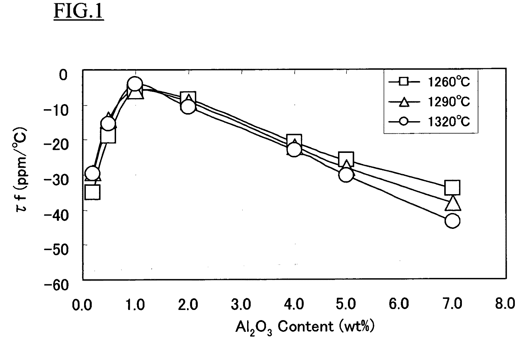
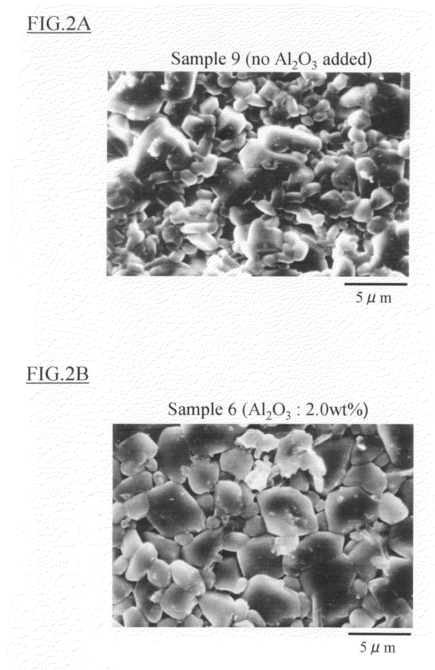
[0064]Except for weighing and blending Al2O3 as a subcomponent with content ratios to the main component materials as shown in Table 2 while using main components with same compositions as Sample 6, a dielectric ceramic composition material was produced as in Example 1. Using the produced dielectric ceramic composition material, a dielectric ceramic composition was produced and evaluated as in Example 1. The results are shown in Table 2.

[0065]Also, the produced dielectric ceramic composition material was added with polyvinyl alcohol as an organic binder, granulated and then press-formed at 2.0 tonf / cm2 to obtain a formed green body with dimensions of 20×5.5×1 mm. The green body was fired in air under conditions of 1290° C.-2h to obtain a sintered body. For sintered body, strength (three-point bend) was measured by the following method.

[0066]Strength

[0067]From the obtained sintered body, a specimen with dimensions of 16.0×4.5×0.8 mm was produced, and a three-point bending test was pe...

example 3

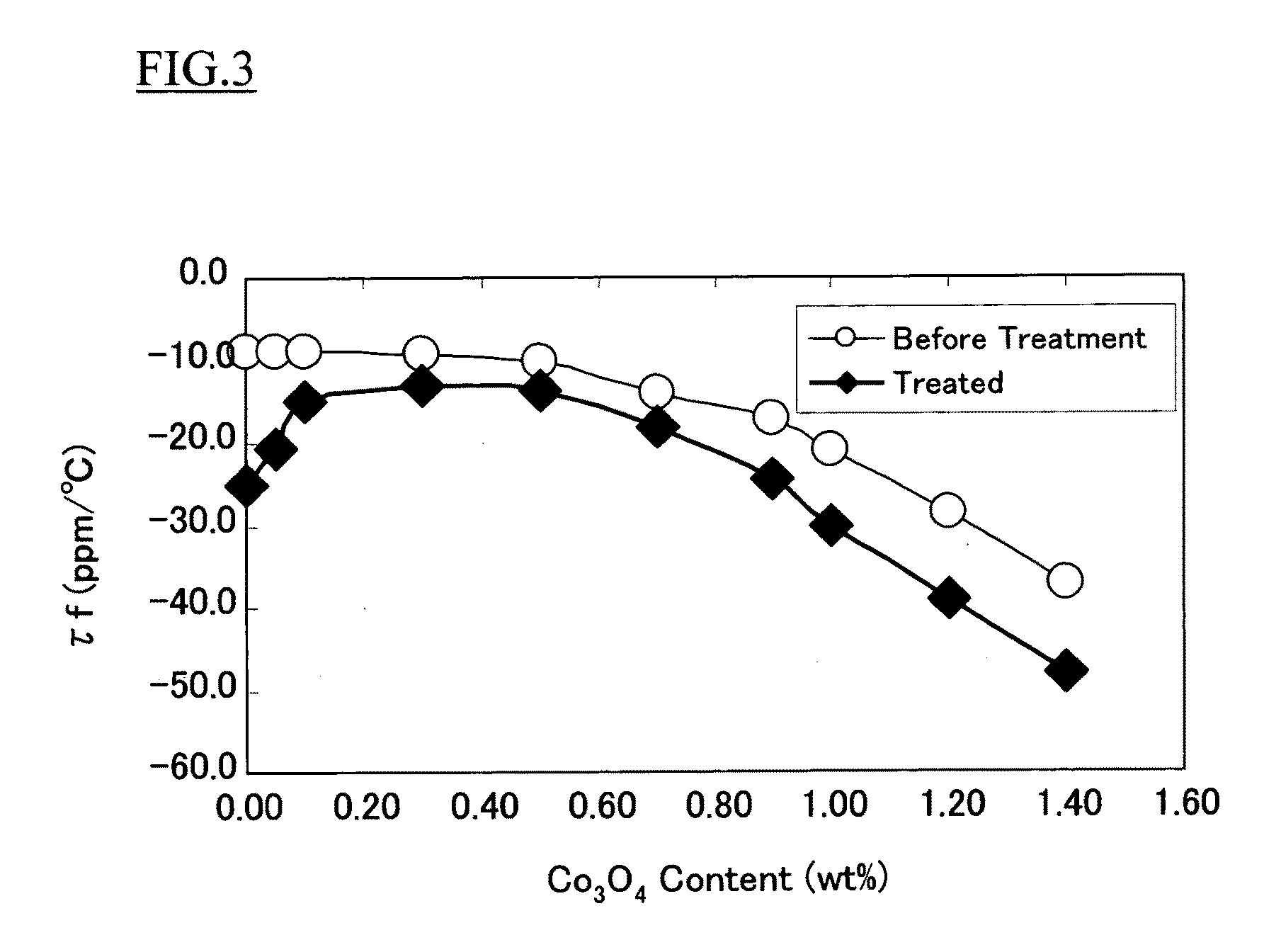
[0069]Except for further weighing and blending Co3O4 as a subcomponent with content ratios shown in Table 3, using same component ratios as Sample 6, a dielectric ceramic composition was produced and evaluated as in Example 1. The results are shown in Table 3. Also, resistance to reduction of the sintered body was measured by the following method.

[0070]Resistance to Reduction

[0071]The obtained sintered body was subject to reduction treatment in a reducing atmosphere with N2-100% (pO2=10 ppm) under conditions of 800° C.-10 min. For samples before and after the treatment, frequency-temperature coefficient τf values were evaluated as in Example 1. Then, amount of change between τf values of samples before and after reduction treatment, and change rate were calculated. As a criterion for evaluation, the amount of change within 65% was defined as being good. The results are shown in Table 4 and FIG. 3. Note that in FIG. 3, white circle indicates τf value before reduction treatment and bl...


PUM

PropertyMeasurementUnit
temperatureaaaaaaaaaa
particle sizeaaaaaaaaaa

Abstract

A dielectric ceramic composition comprising forsterite in an amount of 93.0 to 99.0 mol % when calculating in terms of 2MgO—SiO2 and calcium titanate in an amount of 1.0 to 7.0 mol % when calculating in terms of CaTiO3 as main components, and as a subcomponent, aluminum oxide in an amount of 0.2 to 5 mass % when calculating in terms of Al2O3 per 100 mass % of said main components. According to the present invention, a dielectric ceramic composition, capable of having both low permittivity and good frequency-temperature characteristic as well as ensuring high Qf value and further having sufficient mechanical strength, and suitable to use in an antenna, a filter and the like used in the high-frequency region, can be provided. Also, the present invention allows providing a dielectric ceramic composition further having resistance to reduction in addition to all of the above properties.

Description

FIELD OF THE INVENTION[0001]The present invention relates to a dielectric ceramic composition, and further particularly a dielectric ceramic composition suitable to use in an element for an antenna or an element for a filter such as bandpass filter, used in the high-frequency region.DESCRIPTION OF THE RELATED ART[0002]Recently, with the rapid developments of information-communication technology, a range of frequencies used is expanding to the high-frequency region. As a result, to efficiently use the limited frequency range, it is required to segmentalize the frequencies and to speed up transmission speed, etc. A dielectric ceramic composition, used as an electronic component mounted in a communication device such as a mobile phone, is no exception to this.[0003]Such a dielectric ceramic composition needs to increase a Qf value calculated as a product of a quality factor “Q” and the frequency in use “f” (i.e. high-frequency property); to have low permittivity to prevent delaying tra...

Claims


Application Information

Patent Timeline
Patent Type & Authority Applications(United States)
IPC IPC(8): C04B35/465
CPCC04B35/20C04B2235/9669C04B2235/3213C04B2235/3215C04B2235/3217C04B2235/3236C04B2235/3277C04B2235/3279C04B2235/3418C04B2235/5436C04B2235/656C04B2235/6562C04B2235/6567C04B2235/664C04B2235/786C04B2235/3208C04B35/04C04B35/14
Inventor ABE, MASARUWATANABE, KAKERUNAKANO, RYOHEINIWA, YASUOWATANABE, MATSUMI
Owner TDK CORPARATION
Why Eureka
Try Eureka