Method of forming gas diffusion layer for fuel cell

a technology of gas diffusion layer and fuel cell, which is applied in the manufacture of cell components, final product manufacturing, electrochemical generators, etc., can solve the problems of reducing the size unable to supply air and fuel gas to the respective electrode layers of the fuel cell, and the shape of the cutting die is unlikely to be transferred to the metal sheet, etc., to achieve accurate through hole formation, efficient output, and low pressure loss associated with air or fuel gas flow through the hole

Inactive Publication Date: 2009-04-09
TOYOTA SHATAI KK +1
View PDF2 Cites 12 Cited by
  • Summary
  • Abstract
  • Description
  • Claims
  • Application Information

AI Technical Summary

Benefits of technology

[0008]According to the method of the present invention, the first step and the second step each execute, a plurality of times, the machining cycle consisting of feeding the metal sheet by the predetermined machining pitch and cutting through holes by means of the cutting die, so as to accurately form the through holes each having the desired shape. The first step and the second step are repeated so as to form the gas diffusion layer for a fuel cell. The thus-formed gas diffusion layer for a fuel cell has through holes which are uniform in shape, and a portion of the gas diffusion layer to which the shape of the cutting die is transferred; i.e., a stepped portion of the gas diffusion layer, can be increased in thickness and thus can have a thickness suitable for flow of air or a fuel gas.
[0009]Accordingly, by employing this gas diffusion layer in a fuel cell, pressure loss associated with flow of air or a fuel gas therethrough can be lowered, and thus an electrode layer can be supplied with sufficient air or fuel gas for an electrode reaction. Also, since a large number of through holes can be uniformly formed, generated electricity can be efficiently output to the exterior of the electrode. Thus, the fuel cell can exhibit sufficiently high efficiency in generation of electricity. Also, since there is no need to form, for examp

Problems solved by technology

However, imparting a generally rectangular cross-sectional shape to the conductor hinders reduction in size of the fuel cell.
However, since the above-mentioned conventional metal lath and expanded metal are very thin and involve high resistance to flow of air or fuel gas; i.e., high pressure loss, using the metal lath or expanded metal as a conductor may result in a failure to sufficiently

Method used


Image

  • Method of forming gas diffusion layer for fuel cell
  • Method of forming gas diffusion layer for fuel cell
  • Method of forming gas diffusion layer for fuel cell

Examples


first embodiment

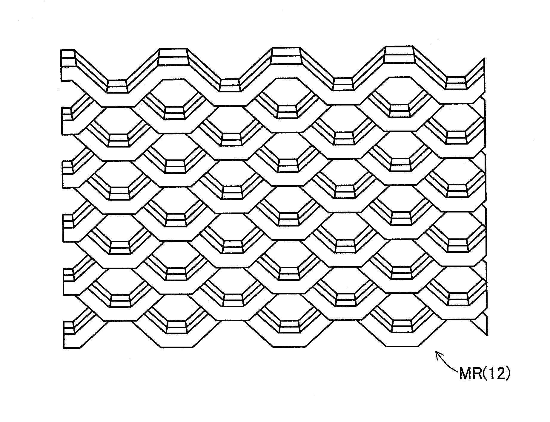
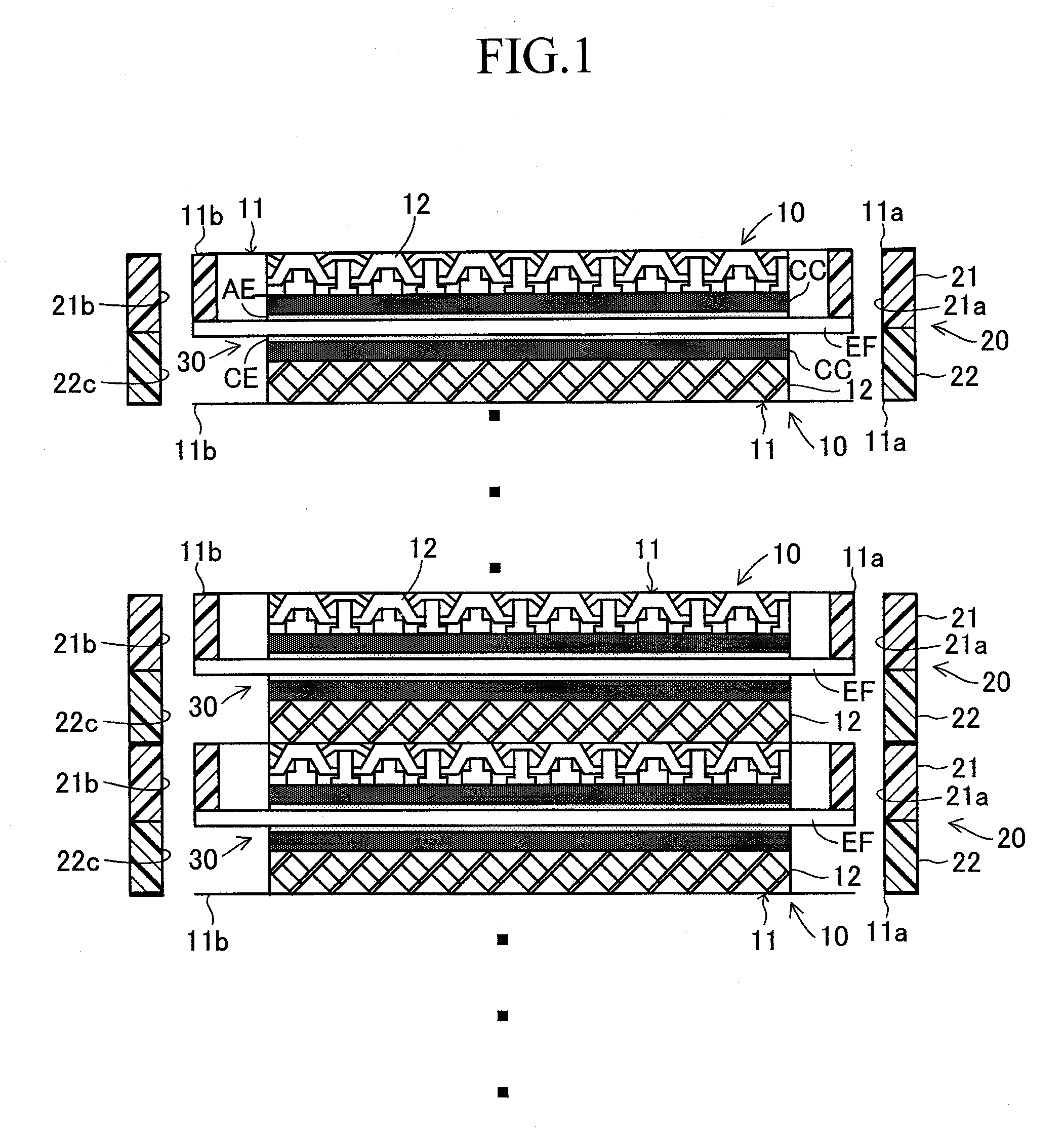
[0023]Embodiments of the present invention will next be described in detail with reference to the drawings. FIG. 1 relates to the present invention, and schematically shows a portion of a polymer electrolyte fuel cell stack which uses separators 10 for a fuel cell (hereinafter, referred to merely as the separators 10). This fuel cell stack is a stack of cells. A single cell includes two separators 10, a frame 20, and an MEA (Membrane-Electrode Assembly) 30. The frame 20 and the MEA 30 are sandwiched between the separators 10. When fuel gas such as hydrogen gas, and oxidizer gas such as air are introduced to the cells from the exterior of the fuel cell stack, electrode reactions occur in the MEAs 30, thereby generating electricity. Hereinafter, fuel gas and oxidizer gas may be collectively referred to as gas. Oxidizer gas may contain water mist for removing heat generated in association with electrode reactions in the MEAs 30 and for maintaining appropriate water content in the MEAs ...

second embodiment

[0054]After the upper blade UH is returned to the original position (in this case, the first machining position), the upper blade UH is moved in a direction opposite that of the preceding movement thereof along the width direction of the stainless steel sheet S; i.e., in this case, from the first machining position to the second machining position, whereat the execution of the third step is completed. Subsequently, while the upper blade UH is positioned at the second machining position, the first step is executed. That is, the first step to be executed after the third step is such that, while the upper blade UH is positioned at the second machining position, the machining cycle is executed two times. The second step to be executed after this first step is such that, while the upper blade UH is positioned at the first machining position, the machining cycle is executed two times. In this case, the third step is such that, while the upper blade UH is positioned at the second machining...


PUM

PropertyMeasurementUnit
Thicknessaaaaaaaaaa
Widthaaaaaaaaaa

Abstract

A collector 12 which serves as a gas diffusion layer for a fuel cell; i.e., a metal lath MR, is formed by a method consisting of a first step and a second step. In the first step, while an upper blade UH is positioned at a first machining position along the width direction of a stainless steel sheet S, generally hexagonal through holes are formed in the stainless steel sheet S at two positions which are biased from each other by a machining pitch. In the second step, while the upper blade UH is positioned at a second machining position along the width direction of the stainless steel sheet S, generally hexagonal through holes are formed in the stainless steel sheet S at two positions which are biased from each other by the machining pitch. The first step and the second step are alternated repeatedly, thereby forming the metal lath MR having a uniform shape and a predetermined thickness.

Description

TECHNICAL FIELD[0001]The present invention relates to a method of forming a gas diffusion layer of metal for use in a fuel cell, particularly, a polymer electrolyte fuel cell.BACKGROUND ART[0002]A conventionally known fuel cell is disclosed in, for example, Patent Document 1. In this conventional fuel cell, a separator composed of a thin, flat substrate and a meshy conductor is disposed between adjacent single cells. The meshy conductor is formed from a lance-cut metal (metal lath) or expanded metal in which diamond-shaped slits are formed. The meshy conductor has a generally rectangular cross-sectional shape. Thus, the meshy conductor provides flow paths for supplying air or fuel gas to an electrode diffusion layer and can lead current to the exterior of the fuel cell.[0003]In the field of development of fuel cells, research efforts have been actively carried out on not only improvement of efficiency in generating electricity but also reduction in the size of a fuel cell. In the ab...

Claims


Application Information

Patent Timeline
IPC IPC(8): H01M8/02
CPCB21D31/043H01M8/023H01M8/0232Y10T29/10H01M2008/1095Y02E60/50H01M8/0254Y02P70/50
Inventor HASHIMOTO, KEIJIKATO, KAZUHIKO
Owner TOYOTA SHATAI KK
Why Eureka
Try Eureka