Shielding gas for hybrid welding and hybrid welding method using the same

a hybrid welding and shielding gas technology, applied in welding/cutting media/materials, welding apparatus, manufacturing tools, etc., can solve the problems of insufficient welding, high cost of shielding gas, and inability to alleviate generated defects, so as to achieve excellent wettability, reduce shielding properties, and prevent pit generation

Inactive Publication Date: 2009-04-16
NIPPON SANSO CORP
View PDF11 Cites 28 Cited by
  • Summary
  • Abstract
  • Description
  • Claims
  • Application Information

AI Technical Summary

Benefits of technology

[0049]The effect can be obtained when using a joint where, for example, three or more galvannealed steel plates are piled, burn-through or hole-formation of the welded metal at the upper side can be prevented by adjusting the gap to the thickness of the top plate or less.
[0050]When high-speed welding is conducted, shielding properties may be lowered. However, If another shielding-gas nozzle is provided ahead of the welding direction, the same effects can be achieved.
[0051]Moreover, according to the present invention, the above mixed gas having the composition is used in lap fillet welding of galvannealed steel plates using a hybrid welding. Therefore, even if the welding method is a type of non-penetration welding and the gap between the steel plates is 0 mm, generation of pits can be prevented, and generation of bead irregularities such as humping frequently occurring in high-speed welding can also be prevented.
[0052]In addition, wettability is excellent and a broader and flat bead can be formed. Accordingly, it was discovered that an effect wherein generation of notches such as undercuts was prevented could be achieved in the present invention.
[0053]Furthermore, a preferred state of welding where generation of spatters is less can be obtained. Therefore, adhesion of spatters to a laser optical member such as protective glass can be suppressed, and the number of times protective glass exchanged can be decreased.
[0054]Additionally, when conducting high-speed welding, shielding properties may be lowered. However, by providing another shielding-gas nozzle ahead of the moving direction, the same effects can be achieved,

Problems solved by technology

As a result, not only blowholes but also pits were generated on the bead surface when only applying the hybrid welding to lap welding of galvannealed steel plates where the gap was zero, and sufficient welding could not be achieved.
Furthermore, even if the shielding gas having a preferable composition disclosed in the patent publication was applied, the generated defects could not be alleviated.
Therefore, the shielding gas is costly.
Furthermore, the shielding gas does not contain an element such as carbon dioxide gas or oxygen gas that promotes stabilisation of arc or discharge of zinc vapor.
Therefore, droplet transfer becomes unstable in hybrid welding of galvannealed steel plates, thereby generating welding defects.
H6-328279, which improves welding qualities in laser welding, As a result, even if 15% to 25% of carbon dioxide gas was simply mixed therein, the bead shape was not stable, and generation of pits could not be suppressed at a sufficient level.
Additionally, even if the volume ratio of the carbon dioxide gas was adjusted to 80% to 95%, as disclosed by Japanese Unexamined Patent Publication No. 2001-138085, generation of pits could not be suppressed at a sufficient level, and generation of spatters was also significant.
Thus, the results were not acceptable.

Method used


Image

  • Shielding gas for hybrid welding and hybrid welding method using the same
  • Shielding gas for hybrid welding and hybrid welding method using the same
  • Shielding gas for hybrid welding and hybrid welding method using the same

Examples


examples

[0114]Hereinafter, the present invention will be further described in detail with reference to Examples.

(Hybrid Welding of a Lapped Joint of a Galvannealed Steel Plate)

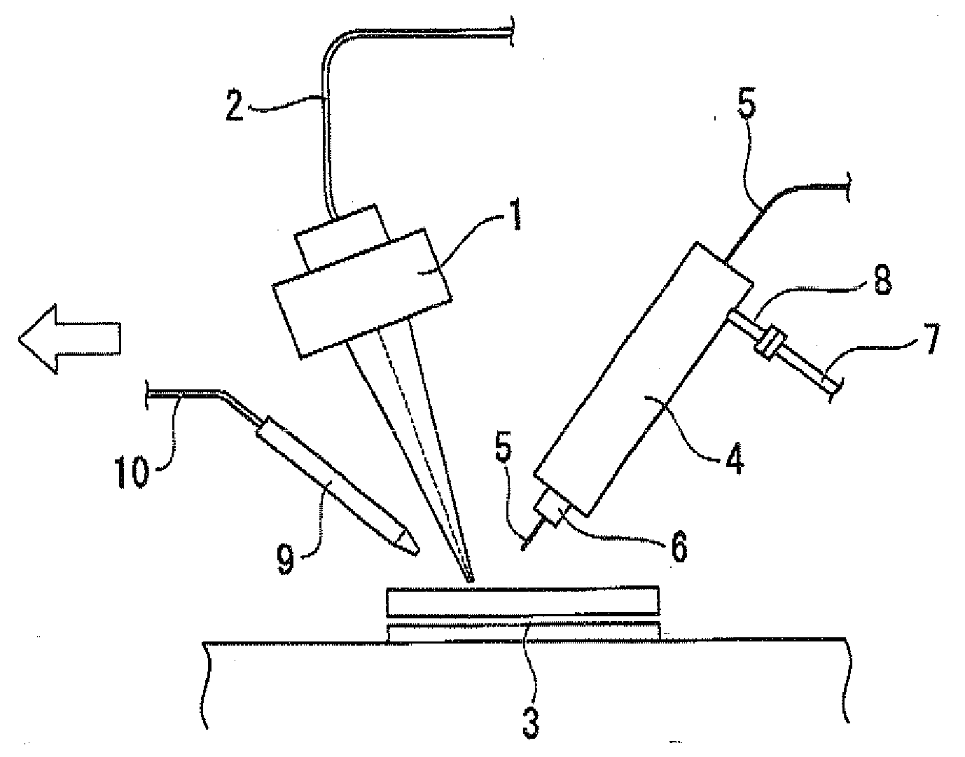
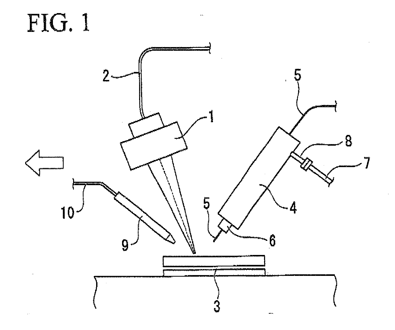
[0115]Hybrid welding was conducted using a shielding gas and a welding machine shown in FIG. 1.

[0116]Welding was conducted with respect to a lap joint where steel plates were piled under the following conditions. The shielding gas was supplied from an arc torch. An alloyed hot dip galvannealed steel plate (the zinc coating weight thereof was 45 g / m2) 0.7 mm thick or 0.8 mm thick, and a cold-reduced steel sheet 1.0 mm thick were used as the welded materials. A three-component-mixed gas including an argon gas, an oxygen gas, and a carbon dioxide gas was used as the shielding gas. These components were mixed at different ratios to produce a plurality of shielding gases having different compositions. Additionally, a case where a gap was provided between steel plates and a case where a gap was not provided therein were als...

experiment 4

(Experiment 4)

[0179]Using two galvannealed steel plates 1.8 mm thick, lap fillet welding was conducted where the gap between the upper and lower plates was 0 mm and the push angle of the arc torch was 20°. The number of pits in a weld length of 100 mm, the presence of bead irregularities where a continuous bead could not be formed due to occurrence of humping or the like, and generation of spatters were confirmed. A three-component mixed gas including an argon gas, a carbon dioxide gas and an oxygen gas was used as the shielding gas, and hybrid welding was conducted while modifying the compositional ratio of the carbon dioxide gas and the oxygen gas in the shielding gas.

[0180]Additionally, comparative examples using an argon gas-carbon dioxide gas-based shielding gas and an argon gas-oxygen gas-based shielding gas that are general shielding gases for MAG welding are shown below.

[0181]When bead irregularities were not present in welded samples, the center of the bead thereof was cut ...

experiment 5

(Experiment 5)

[0210]Using a cold-reduced steel sheet 1.2 mm thick as a upper plate and a galvannealed steel plate 1.6 mm thick as a lower plate, lap fillet welding was conducted where the gap between the upper and lower plates was 0 mm and the push angle of the arc torch was 20°. In the same manner as Experiment 4, the number of pits in a weld length of 100 mm, presence of bead irregularities where a continuous bead could not be formed due to occurrence of humping or the like, and generation of spatters was confirmed.

[0211]A three-component mixed gas including an argon gas, a carbon dioxide gas and an oxygen gas was used as the shielding gas, and hybrid welding was conducted while modifying the compositional ratio of the carbon dioxide gas and the oxygen gas in the shielding gas. Additionally, an Ar—CO2-based shielding gas and an Ar—O2-based shielding gas that are general shielding gases for MAG welding were used as comparative experiments.

[0212]When bead irregularities were not pre...


PUM

PropertyMeasurementUnit
melting pointaaaaaaaaaa
wavelengthaaaaaaaaaa

Abstract

A shield gas for use in welding of galvanized steel sheet with the simultaneous use of laser welding and arc welding, wherein, providing that A refers to the vol. % of carbon dioxide gas and B to the vol. % of oxygen gas in the shield gas, in the event of overlapped welding of steel sheets, at least one of which is a galvanized steel sheet, when the gap between the steel sheets is 0, 15≦A≦50, 5≦B≦9 and B≧21−0.8A, when the ratio of G/T, in which G is the gap between the steel sheets and T the thickness of the steel sheet positioned on the side of welding torch, is 1 or below and when the thicknesses of the steel sheets are identical with each other, 15≦A≦50, 3≦B≦9 and B≧0.1A, and when the ratio of G/T is 1 or below and when the thicknesses of the steel sheets are different from each other, 10≦A≦50, 3≦B≦9 and B≧0.1A and B≧15−0.6A, and in the event of overlapped fillet welding, when both the steel sheets to be welded are galvanized steel sheets, 3≦A≦25, 5≦B≦13 and B≧10−0.33×A, and when one of the steel sheets to be welded is a galvanized steel sheet, 3≦A≦25, 5≦B≦13 and B≧10.5−0.5×A, the balance being argon gas.

Description

TECHNICAL FIELD[0001]The present invention relates to a hybrid welding method applied to a galvannealed steel plate, The present invention specifically relates to a welding method and a shielding gas used therefore that can prevent surface defects (pits) and burn-through that generate on the bead surface in lap welding. Furthermore, the present invention specifically relates to a welding method and a shielding gas used in the welding method that exhibit few bead irregularities (defects in formation of a continuous bead) due to humping or the like in lap fillet welding and that can further prevent pits or undercuts from generating on the bead surface.[0002]This application claims the priority of Japanese Patent Application Nos. 2006-041091 and 2006-041092, filed on Feb. 17, 2006, the contents of which are incorporated herein by reference.BACKGROUND ART[0003]A galvannealed steel plate is a steel plate that is subjected to a rust-proofing treatment mainly using zinc. Because the galvan...

Claims


Application Information

Patent Timeline
Patent Type & Authority Applications(United States)
IPC IPC(8): B23K26/00
CPCB23K26/1429B23K26/243B23K26/3206B23K2203/04B23K28/02B23K35/38B23K26/3293B23K26/32B23K26/242B23K26/348B23K2101/34B23K2103/04B23K2103/08B23K2103/50
Inventor KAMEI, TOSHIKAZU
Owner NIPPON SANSO CORP
Why Eureka
Try Eureka