Electric wind adjustable fresnel reflector solar concentrator

a solar concentrator and solar energy technology, applied in solar heat systems, sustainable buildings, light and heating equipment, etc., can solve the problems of high power consumption, large amount of pollution by-products, and no prior art was found in the field of positioning and motion

Inactive Publication Date: 2009-04-23
RABINOWITZ MARIO
View PDF23 Cites 2 Cited by
  • Summary
  • Abstract
  • Description
  • Claims
  • Application Information

AI Technical Summary

Benefits of technology

[0045]In the Electric Wind adjustable Fresnel reflector solar concentrator that has been developed, the Electric Wind aligns the optical elements to concentrate solar energy on a receiver having dimensions small compared to the dimensions of the array. This permits the focal point of the array to remain focused on the receiver over the course of a day and throughout the year.

Problems solved by technology

No prior art was found related to positioning and motion control by electrons, ions and neutrals in electric fields of adjustable reflecting elements in a Fresnel reflector solar concentrator.
They operate at very high levels of power consumption, and utilize exotic types of propellants, producing large amounts of pollution by-products.
Except for applications in outer space such devices are for the most part not practical due to their size, weight and power requirements.
No prior art was found that utilized field emission for force production in a Fresnel reflector solar concentrator.

Method used


Image

  • Electric wind adjustable fresnel reflector solar concentrator
  • Electric wind adjustable fresnel reflector solar concentrator
  • Electric wind adjustable fresnel reflector solar concentrator

Examples


Embodiment Construction

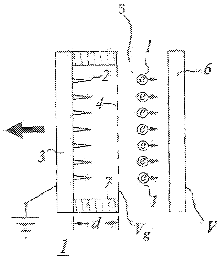
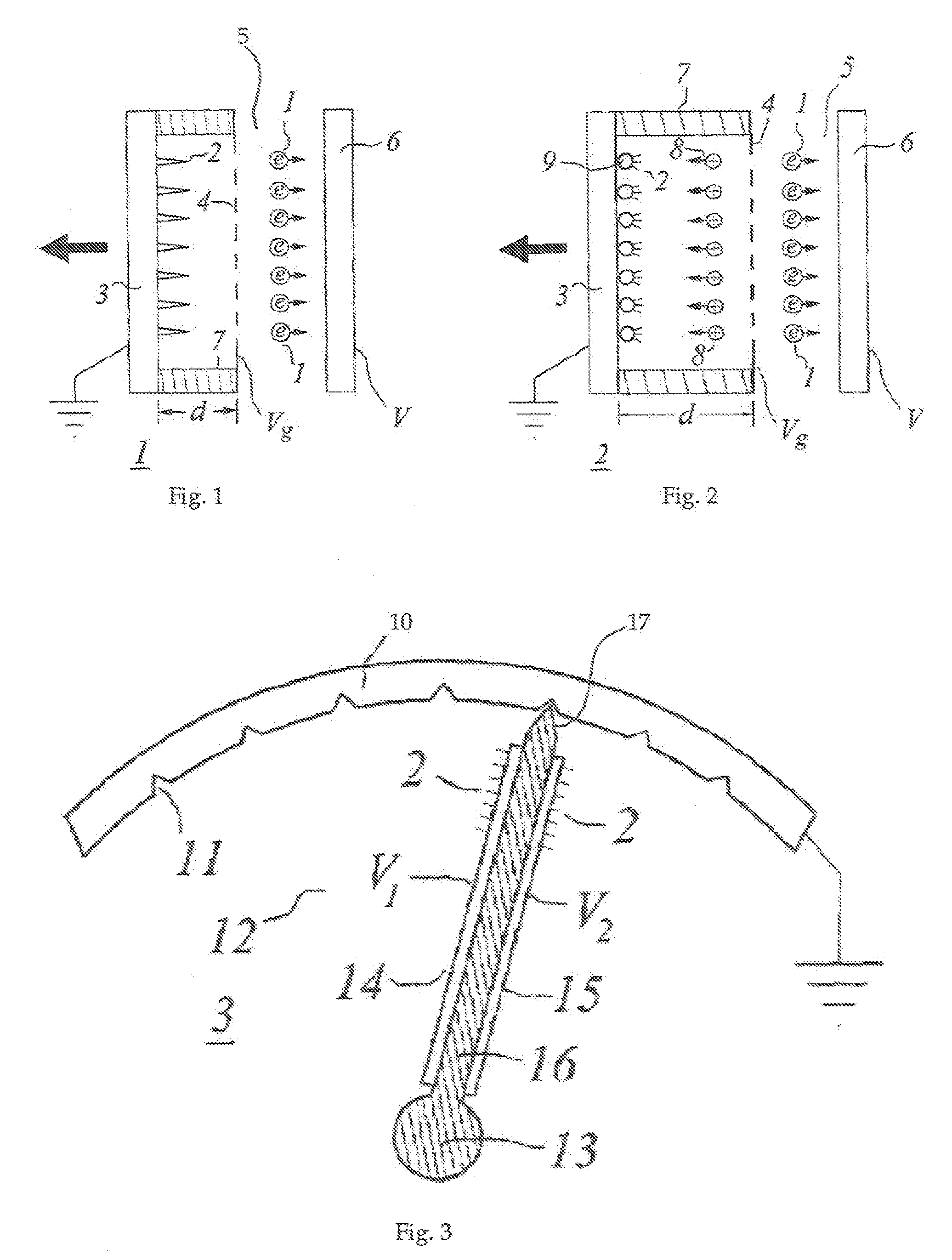
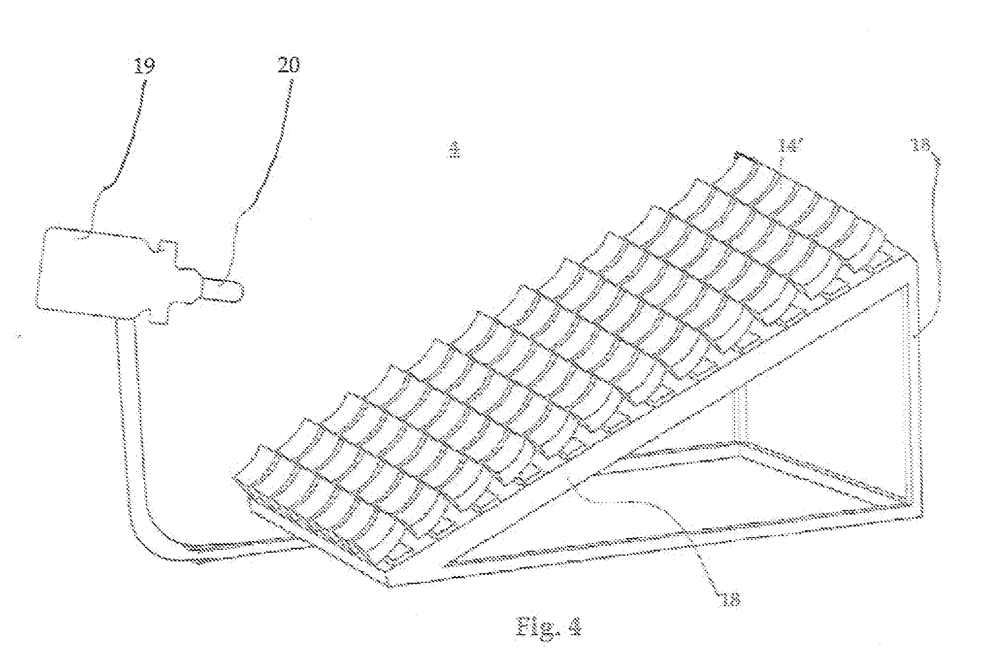
[0119]As is described here in detail, the objectives of the instant invention may be accomplished by any of a number of ways separately or in combination, as taught by the instant invention. A tracking solar concentrator has been developed in which the orientation of individual optical elements (mirrors, reflectors, lenses) is accomplished by creating an electric wind to align them consecutively or concurrently without the need for expensive, bulky, and heavy motors. Thus the improved solar concentrator of the instant invention can be more reliable and lighter than conventional solar arrays.

[0120]FIG. 1 shows a cross-sectional view of one embodiment of an electric wind motive device 1, which in this case produces a force by the emission of electrons 1 from whiskers 2 on an electrode 3 that serves as cathode. Upon leaving the whiskers 2, the electrons 1 cross the gap d to pass through a grid 4 at voltage Vg to enter a region 5, and then are collected at the ultimate anode collector p...


PUM


Abstract

This invention deals with novel method and apparatus for positioning and motion control of the elements (mirrors) of a Fresnel reflector solar concentrator tracking heliostat array by rapid-response motorless linear motion, angular deflection, and rotational motion utilizing electric wind force due to electrons, ions, and/or neutrals. Thus forces and torques are produced without the use of internal moving parts. Control is achieved without recourse to magnetic fields, by means of high electric fields which may be attained at relatively low voltages. At low voltages, the instant invention exceeds the capability of conventional systems. It can perform dynamic motion control over a wide range of dimensions and signal bandwidth with independent amplitude and frequency modulation. It is ideally suited for maximization of solar energy focused by the array onto a receiver. Since there are no internal moving parts, the instant invention is the most adapted for fabrication at the micro and nanotechnology realms. Furthermore it provides less costly and greater ease of manufacture from the nano-to the macro-realm.

Description

FILED OF THE INVENTION[0001]This invention provides a better means to achieve affordable solar energy than by a conventional tracking heliostat array. In the latter, enabling the optical elements to be movable generally requires many large heavy motors that consume a great deal of power. This results in an expensive, bulky, and ponderous heliostat that is unfavorable for rooftop and other applications where much weight cannot be tolerated. The present invention functions in solar concentrators and similar equipment much the same as parabolic dish and parabolic trough concentrators, without their disadvantages of bulk and weight. The angular alignment of the optical elements (mirrors, refractors, lenses, etc.) is accomplished by a rocket-like thrust of an Electric Wind rather than with cumbersome motors.BACKGROUND OF THE INVENTION [0002]The instant invention related generally to larger scale Solar Energy Concentrators than for example in the U.S. Pat. No. 7,133,183 by M. Rabinowitz. ...

Claims


Application Information

Patent Timeline
Patent Type & Authority Applications(United States)
IPC IPC(8): F24J2/40
CPCF24J2/08F24J2/10F24J2/38F24J2/40F24J2/07Y02B10/20Y02E10/47Y02E10/41F24J2002/108F24S20/20F24S23/30F24S23/70F24S50/00F24S50/20F24S2023/872H01L31/0547Y02E10/52Y02E10/40
Inventor RABINOWITZ, MARIO
Owner RABINOWITZ MARIO
Why Eureka
Try Eureka