Multi-layered foamed polymeric objects and related methods

a polymer object and polymer technology, applied in the field of foamed thermoplastic materials with multi-layered structure, to achieve the effect of first bulk crystallinity level

Active Publication Date: 2009-04-23
DART CONTAINER +1
View PDF16 Cites 56 Cited by
  • Summary
  • Abstract
  • Description
  • Claims
  • Application Information

AI Technical Summary

Benefits of technology

[0013]In another embodiment, the invention is directed to a method for making a multi-layer foamed polymeric object (such as, for example, a cup or tray) from a solid monolithic thermoplastic material sheet, the thermoplastic material sheet having a first bulk crystallinity level, the method comprising: absorbing an effective amount of a plasticizing gas into the thermoplastic material sheet to yield a reversibly plasticized thermoplastic material sheet, the plasticized thermoplastic material sheet being impregnated with the plasticizing gas and having a second bulk crystallinity level that is greater than the first bulk crystallinity level; desorbing at least some of the plasticizing gas from the plasticized thermoplastic material sheet; heating the plasticized thermoplastic material sheet to yield a foamed thermoplastic material sheet, the foamed thermoplastic material sheet having a third bulk crystallinity level that is greater than or equal to the second bulk crystallinity level; and forming or thermoforming the foamed thermoplastic material sheet to yield the multi-layer foamed polymeric object, the multi-layer foamed polymeric object having a fourth bulk crystallinity level that is greater than or equal to the third bulk crystallinity level.
[0014]In yet another embodiment, the invention is directed to a method for making a shaped multi-layer foamed polymeric article of manufacture (such as, for example, a cup or tray) from a solid monolithic thermoplastic material sheet, wherein the thermoplastic material sheet has a first bulk crystallinity level. In this embodiment, the method comprises at least the following steps: absorbing a plasticizing gas into the thermoplastic material sheet, the step of absorbing occurring at a first selected pressure, temperature, and period of time sufficient to yield a reversibly plasticized thermoplastic material sheet, the plasticized thermoplastic material sheet being...

Problems solved by technology

Moreover, in conventional foam production technology, ozone-damaging chlorofluorocarbons (CFCs) or hydrochlorofluorocarbons (HCFCs), as well as flammable hydrocarbons are typically used as foaming agents.
Th...

Method used


Image

  • Multi-layered foamed polymeric objects and related methods
  • Multi-layered foamed polymeric objects and related methods
  • Multi-layered foamed polymeric objects and related methods

Examples


example 1

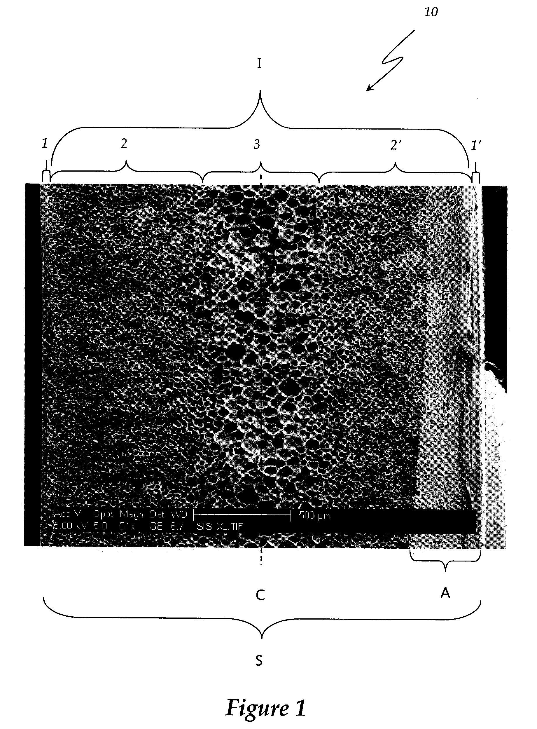
[0046]A 3.8 cm diameter circular section of polymer was punched from 0.107 cm thick sheet of recycled PET (RPET) acquired from LaVergne (The LaVergne Group, Canada). The polymer was then wrapped in a paper towel and placed in a pressure vessel (˜21° C.) at 5.0 MPa for 72 hours for the purpose of carbon dioxide absorption. After absorption, the polymer was transferred to a freezer (˜0° C.) for 24 hours to allow carbon dioxide desorption. The polymer was then removed and placed at room temperature (˜20° C.) for one hour for further desorption. The polymer was then heated (˜100° C.) in a silicon bath for 30 seconds to initiate foaming. FIG. 1 is a scanning electron micrograph showing a partial cross-sectional view from the center of the thermoformed circular polymer section manufactured using the above procedure.

example 2

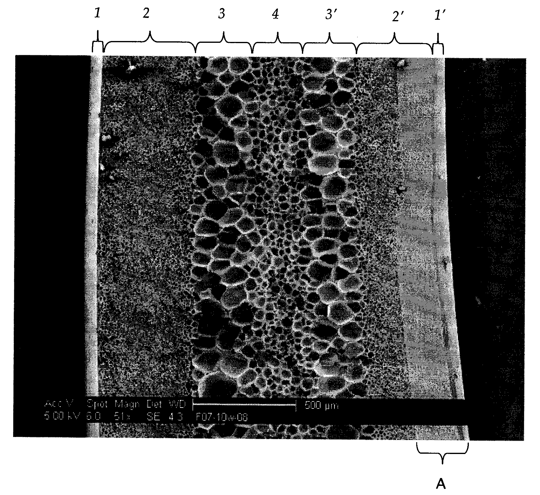
[0047]A 3.8 cm diameter circular section of polymer was punched from 0.107 cm thick sheet of recycled PET (RPET) acquired from LaVergne (The LaVergne Group, Canada). The polymer was then wrapped in a paper towel and placed in a pressure vessel (˜21° C.) at 5.0 MPa for 36 hours for the purpose of carbon dioxide absorption. After absorption, the polymer was transferred to a freezer (˜0° C.) for 24 hours to allow carbon dioxide desorption. The polymer was then removed and placed at room temperature (˜20° C.) for one hour for further desorption. The polymer was then heated (˜100° C.) in a silicon bath for 30 seconds to initiate foaming. FIG. 7 is a scanning electron micrograph showing a partial cross-sectional view from the center of the thermoformed circular polymer section manufactured using the above procedure.

example 3

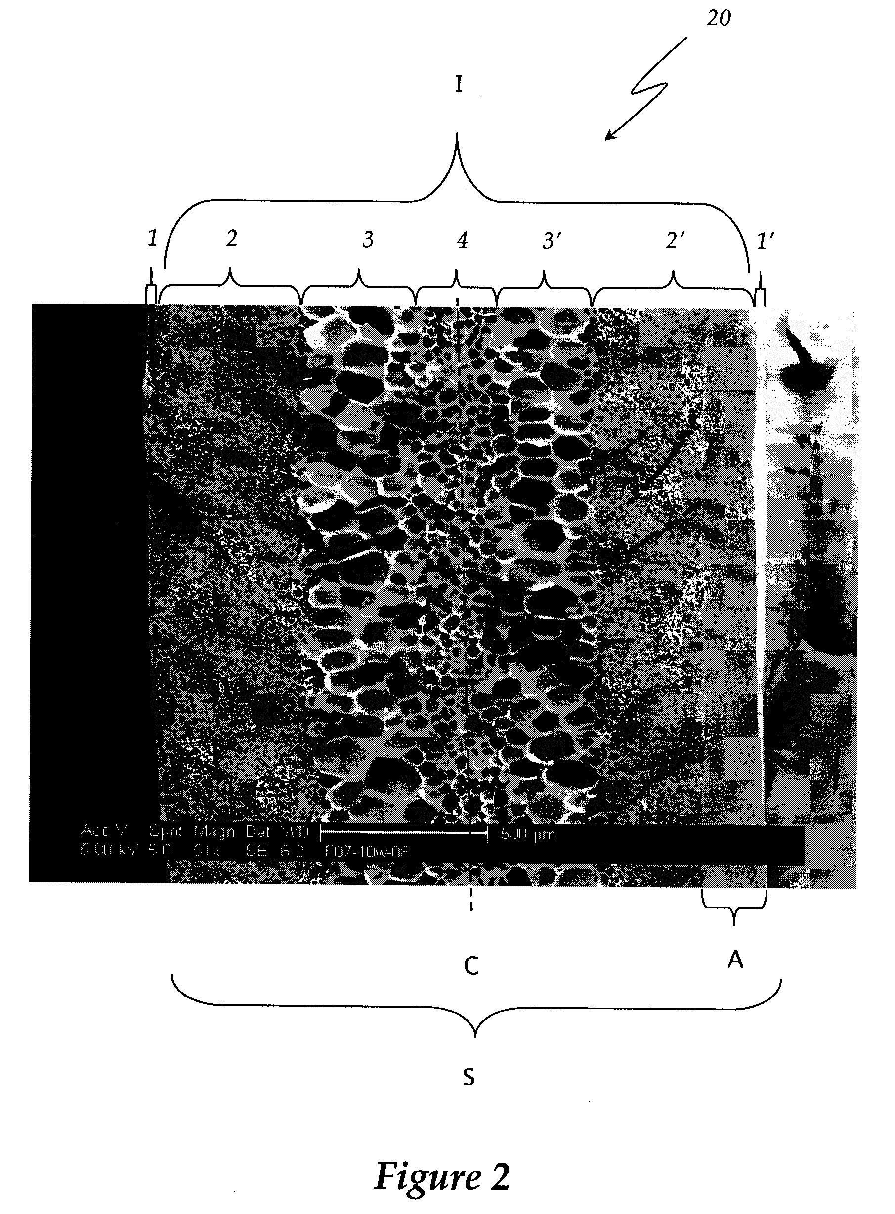
[0048]A 10 cm×15 cm rectangular section of polymer was cut from 0.107 cm thick sheet of recycled PET (RPET) acquired from LaVergne (The LaVergne Group, Canada). The polymer was then wrapped in a paper towel and placed in a pressure vessel (˜21° C.) at 5.0 MPa for 49 hours for the purpose of carbon dioxide absorption. After absorption, the polymer was transferred to a freezer (˜0° C.) for 24 hours to allow carbon dioxide desorption. The polymer was then removed and placed at room temperature (˜20° C.) for one hour for further desorption. The polymer was then loaded into a thermoformer clamping frame, wherein the polymer was heated (˜110° C.) using infrared heat for 8 seconds and simultaneously stretched to initiate foaming. FIG. 8 is a scanning electron micrograph showing a partial cross-sectional view from the center portion of a thermoformed rectangular polymer section manufactured using the above procedure.


PUM

PropertyMeasurementUnit
Temperatureaaaaaaaaaa
Fractionaaaaaaaaaa

Abstract

The invention disclosed herein relates to relates to foamed thermoplastic material objects and articles of manufacture having an internal layered cellular structure, as well as to methods of making the same. In one embodiment, the invention is directed to a multi-layer foamed polymeric article of manufacture, comprising: a non-laminated multi-layer thermoplastic material sheet, wherein the multi-layer thermoplastic material sheet has first and second discrete outer layers sandwiching a plurality of discrete inner foamed layers, and wherein the two outer layers and plurality discrete inner foamed layers are integral with one another. The thermoplastic material may be a semi-crystalline polymer such as, for example, PET (polyethylene terephthalate), PEEK (polyetheretherketone), PEN (polyethylene napthalate), PBT (polybutylene terephthalate), PMMA (polymethyl methacrylate), PLA (polylactide), polyhydroxy acid (PHA), thermoplastic urethane (TPU), or blends thereof. The two outer layers may be unfoamed skin layers having smooth outer surfaces, and the discrete inner foamed layers may be microcellular.

Description

CROSS-REFERENCE TO RELATED APPLICATIONS[0001]This application claims the benefit of U.S. Provisional Application No. 60 / 885,374 filed on Jan. 17, 2007, and U.S. Provisional Application No. 60 / 886,506 filed on Jan. 24, 2007, both of which are incorporated herein by reference in their entireties for all purposes.TECHNICAL FIELD[0002]The present invention relates generally to foamed plastic materials and, more specifically, to microcellular foamed thermoplastic material objects and articles of manufacture having a multi-layered structure, as well as to methods of making the same.BACKGROUND OF THE INVENTION[0003]Microcellular plastic foam refers to a polymer that has been specially foamed so as to create micro-pores or cells (also sometime referred to as bubbles). The common definition includes foams having an average cell size on the order of 10 microns in diameter, and typically ranging from about 0.1 to about 100 microns in diameter. In comparison, conventional plastic foams typicall...

Claims


Application Information

Patent Timeline
IPC IPC(8): B32B5/22B29C44/06
CPCB29C44/3415B29C44/3446B29C44/3453B29C44/3473B29L2031/7132Y10T428/2495B32B27/06Y10T428/24992Y10T428/1376Y10T428/24628B32B5/32Y10T428/249976Y10T428/24998Y10T428/249961Y10T428/249989Y10T428/249979Y10T428/249978Y10T428/249981Y10T428/249977B29C44/0461B29C44/0484B29C44/06B29C44/0415
Inventor NADELLA, KRISHNABRANCH, GREGORY L.KUMAR, VIPINWAGGONER, MICHAEL A.
Owner DART CONTAINER
Why Eureka
Try Eureka