Technology for Cleaning Thermal Fatigue Cracks in Nickel-Based Superalloys With a High Chromium Content

Inactive Publication Date: 2009-04-30
SIEMENS AG
View PDF5 Cites 4 Cited by
  • Summary
  • Abstract
  • Description
  • Claims
  • Application Information

AI Technical Summary

Benefits of technology

[0004]An object of the present invention, therefore is to specify a cleaning method of the type

Problems solved by technology

Gas turbine components and, in particular, the turbine blades are exposed during operation, on account of the prevailing high temperatures and cyclic stresses, to pronounced loads which often result in the formation of thermal fatigue cracks.
The known fluoride ion cleaning, however, is only inadequately capable of cleaning cracks in nickel-based sup

Method used


Image

  • Technology for Cleaning Thermal Fatigue Cracks in Nickel-Based Superalloys With a High Chromium Content
  • Technology for Cleaning Thermal Fatigue Cracks in Nickel-Based Superalloys With a High Chromium Content
  • Technology for Cleaning Thermal Fatigue Cracks in Nickel-Based Superalloys With a High Chromium Content

Examples


Embodiment Construction

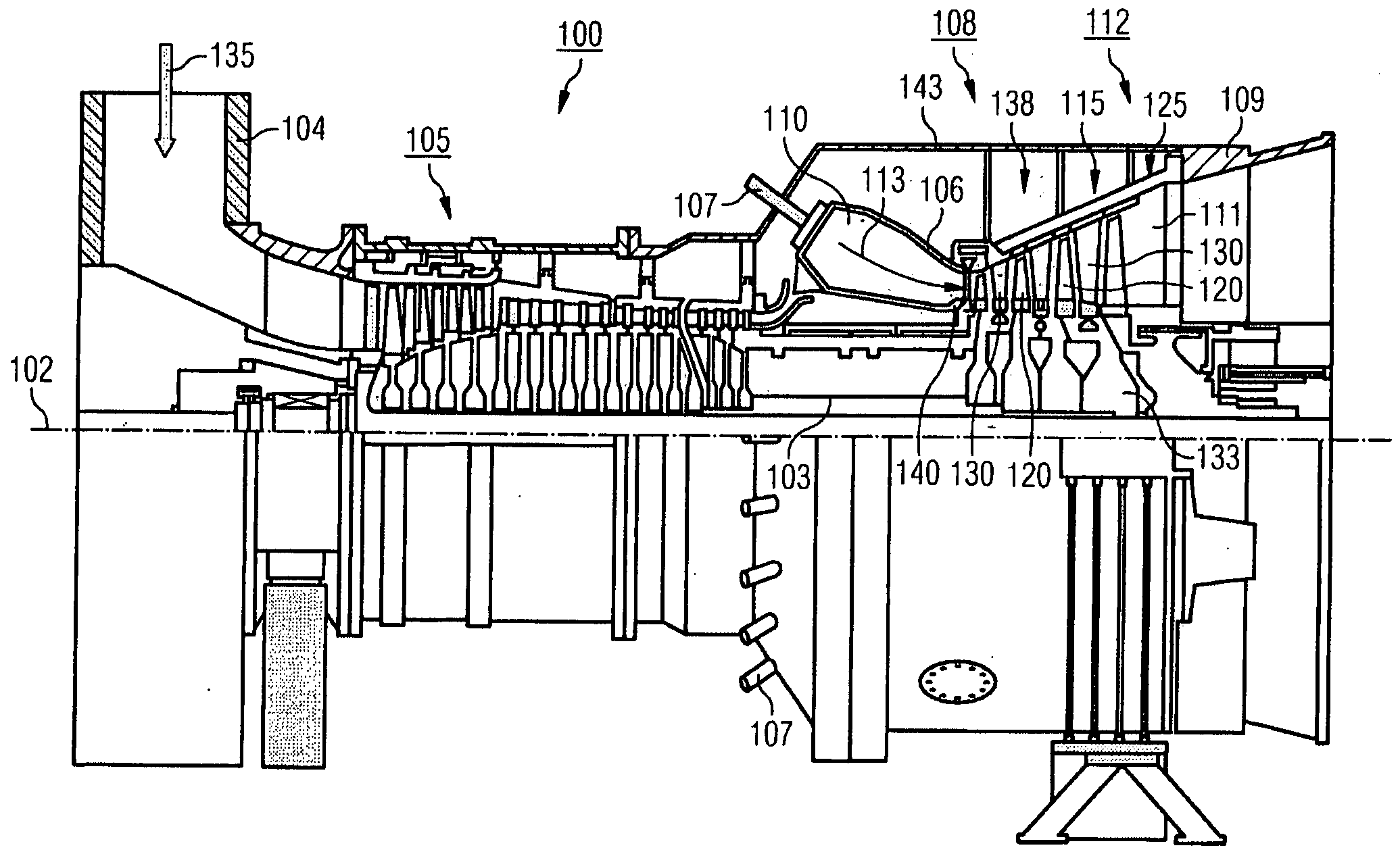
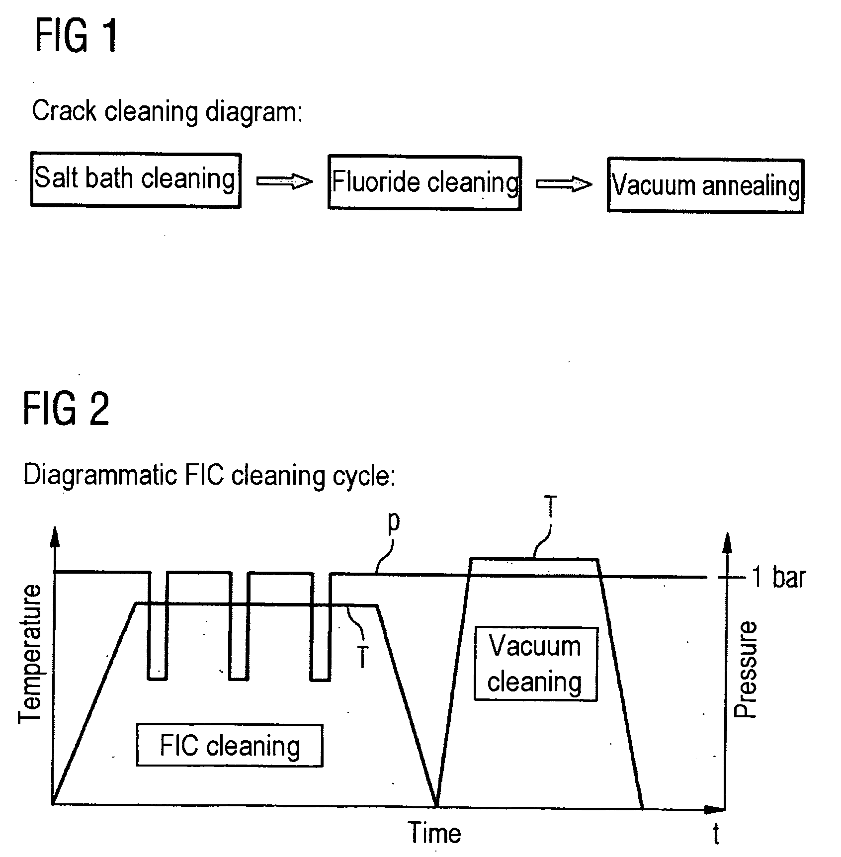
[0018]FIGS. 1 and 2 illustrate diagrammatically a method according to the invention for cleaning components which have cracks contaminated with oxides. The method is suitable particularly for cleaning moving blades and guide vanes 120, 130 of a gas turbine 100 and other components subjected to high stress during operation, such as, for example, the heat shield elements 150 of a combustion chamber 110 of the gas turbine 100. The method comprises the three segments of precleaning, fluoride ion cleaning and vacuum annealing. The precleaning, which is optional, but not absolutely necessary, and may consist, for example, of salt bath cleaning, serves for freeing the surface of the component 120, 130, 155 to be cleaned of superficial oxides and other corrosion products or for damaging these such that the subsequent fluoride ion cleaning can take place in an improved way.

[0019]After pretreatment, the component 120, 130, 155 is subjected to fluoride ion cleaning (FIC). During this FIC clean...


PUM

PropertyMeasurementUnit
Temperatureaaaaaaaaaa
Timeaaaaaaaaaa

Abstract

There is described a method for cleaning components that comprise cracks that are polluted with oxides, in particular gas turbine part. In said method, the components to be cleaned are exposed in a cleaning chamber at high temperature to a cleaning gas containing gaseous halogen compounds, which ionize to form halide ions. A cleaning gas is used containing 18 to 30% by volume hydrogen halide.

Description

CROSS REFERENCE TO RELATED APPLICATIONS[0001]This application is the US National Stage of International Application No. PCT / EP2006 / 067150, filed Oct. 6, 2006 and claims the benefit thereof. The International Application claims the benefits of German application No. 10 2005 051 310.7 DE filed Oct. 26, 2005, and European Patent Office application No. 06004538.2 EP filed Mar. 6, 2006, all of the applications are incorporated by reference herein in their entirety.FIELD OF INVENTION[0002]The present invention relates to a method for cleaning components, in particular gas turbine parts, having cracks contaminated with oxides in which the components to be cleaned are acted upon under the action of temperature in a cleaning chamber with a cleaning gas containing gaseous halogen compounds which dissociate to form halide ions.BACKGROUND OF INVENTION[0003]Gas turbine components and, in particular, the turbine blades are exposed during operation, on account of the prevailing high temperatures a...

Claims


Application Information

Patent Timeline
IPC IPC(8): F26B3/00
CPCC23G5/00Y02T50/67F01D25/002F01D5/005Y02T50/60
Inventor HEINECKE, BRIGITTEOTT, MICHAEL
Owner SIEMENS AG
Why Eureka
Try Eureka