Thermochemical synthesis of fuels for storing thermal energy

a technology of thermal energy and fuel, which is applied in the direction of gaseous fuel, catalyst activation/preparation, energy input, etc., can solve the problems of structural transition (or phase change) of these materials, fundamental challenges remain, and inability to achieve large-scale energy storage technologies

Inactive Publication Date: 2009-04-30
CALIFORNIA INST OF TECH
View PDF9 Cites 19 Cited by
  • Summary
  • Abstract
  • Description
  • Claims
  • Application Information

AI Technical Summary

Benefits of technology

[0005]In one embodiment, the present invention provides a method for preparing a fuel, by heating a reactive oxide substrate to a first temperature, such that the reactive oxide substrate is reduced, wherein the reactive oxide substrate includes a ce

Problems solved by technology

Despite these efforts, large-scale energy storage technologies remain elusive.
While development activities are ongoing in both classes, several fundamental challenges remain.
In particular, key obstacles are connected to the structural transition (or change in phase) that these materials undergo in transforming between oxidized and r

Method used


Image

  • Thermochemical synthesis of fuels for storing thermal energy
  • Thermochemical synthesis of fuels for storing thermal energy
  • Thermochemical synthesis of fuels for storing thermal energy

Examples


example 1

Preparation of Reactive Oxide Substrate

[0069]Sm0.15Ce0.85O1.925 (NexTech SDC15, surface area=32 m2 g−1) was ball milled with 30 wt % starch in ethanol, uniaxially pressed into a pellet, and sintered at 1500° C. for 24 h. The pellet was then lightly crushed and sieved to obtain particle size between 150 and 500 μm. 10 wt % Ni-SDC was prepared via wetness impregnation by dissolving the appropriate amount of Ni(NO3)2.6H2O. After calcining at 750° C., the powder was sintered at 1350° C. for 24 h, pressed into a pellet, lightly crushed, and sieved as described above. SDC without the addition of metal catalyst was also prepared identically as the 10 wt % Ni-SDC.

[0070]The above method was followed for the preparation of 2 wt % Pt—Sm0.15Ce0.85O1.925 using (NH3)4Pt(NO3)2 and 2 wt % Rh—Sm0.15Ce0.8SO1.925 using Rh(NO3)3.2H2O.

example 2

Preparation of CO and Syngas Fuels

[0071]Samples containing 1000 mg of SDC were loaded into a 10 mm diameter continuous flow packed bed reactor with the particles held in place by a porous quartz frit. Reaction gases were delivered by digital mass flow controllers, and the effluent gas was measured by a Varian CP-4900 gas chromatograph equipped with PoraPak Q and Molecular Sieve 5A columns. H2, CH4, CO and CO2 concentrations were converted to flow rates using an internal N2 standard, which also served as a diluent. In some cases, Ar was also used as a diluent. GC calibration curves were established using analytical grade premixed gases.

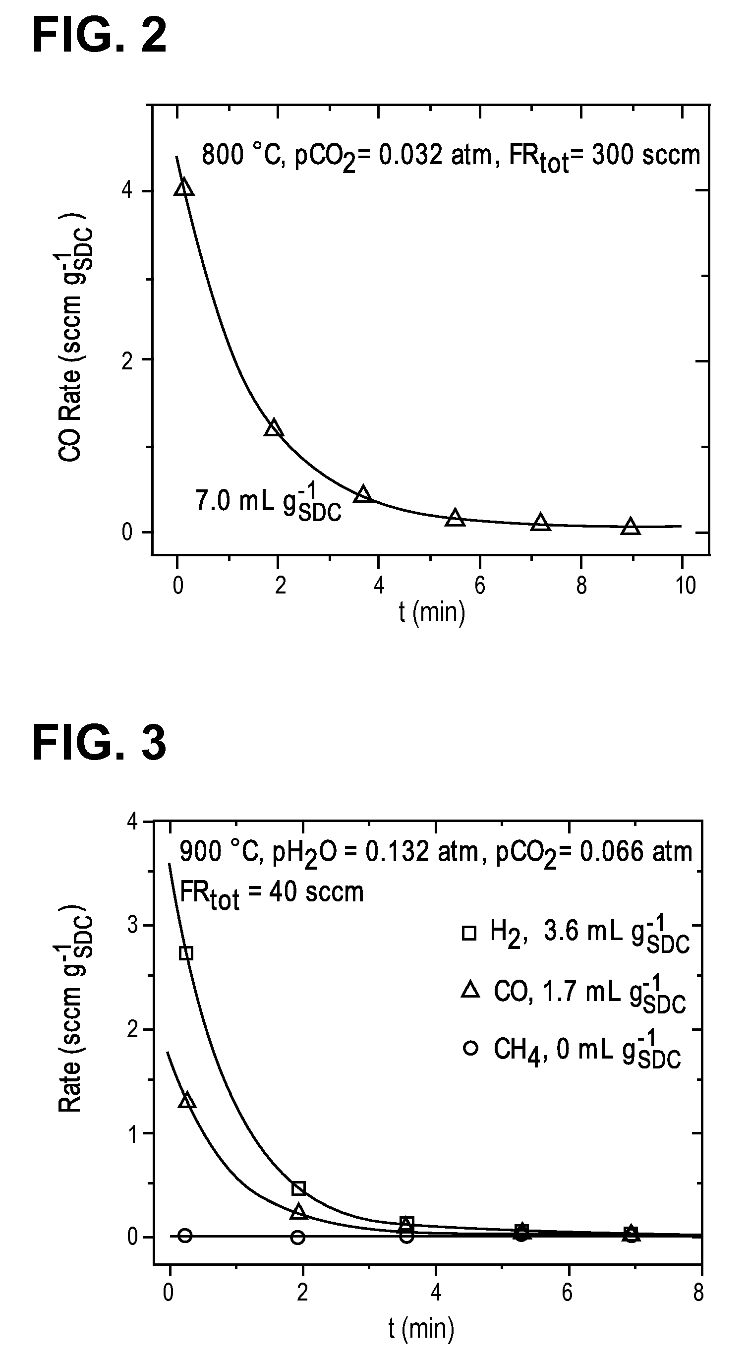
[0072]The reduction of ceria was achieved by flowing a mixture of H2, H2O, and Ar at either Po2=2.0×10⁻²¹ atm at 800° C. or 3.8×10⁻¹⁸ atm at 900° C. Humidification was achieved by bubbling the reaction gas through a H2O bubbler inside a temperature controlled bath. The oxidation of ceria was achieved by passing diluted water vapor, carbon dioxide, sepa...

example 3

Preparation of Methane

[0073]The method of Example 2 was followed using 10 wt % Ni—Sm0.15Ce0.85O1.925 at 400° C. for the oxidation step.


PUM

PropertyMeasurementUnit
Fractionaaaaaaaaaa
Fractionaaaaaaaaaa
Fractionaaaaaaaaaa

Abstract

The present invention provides a method for storing thermal energy, such as solar energy, as a fuel, by heating a reactive oxide substrate to a first temperature, such that the reactive oxide substrate is reduced, wherein the reactive oxide substrate includes a cerium oxide. The method also includes contacting the reduced reactive oxide substrate at a second temperature with a gas mixture including carbon dioxide, wherein the first temperature is greater than the second temperature, thereby preparing the fuel. The present invention also provides a method for preparing the reactive oxide substrates by heating a mixture including a doped cerium oxide and a pore-forming agent, such that pores are formed in the doped cerium oxide, thereby forming the reactive oxide substrate.

Description

CROSS-REFERENCES TO RELATED APPLICATIONS[0001]This application claims the benefit of U.S. Provisional Application No. 61 / 000,500, filed Oct. 26, 2007, incorporated herein in its entirety for all purposes.BACKGROUND OF THE INVENTION[0002]To enable the transition away from a fossil-fuel based energy economy, it is essential to address the problem of energy storage in addition to that of energy extraction from sustainable resources. In particular, if one is to utilize solar energy, a resource that is available in large excess relative to current consumption rates, the photon energy must be stored and made available for use after dark. Several possibilities are already being pursued in laboratories across the world including high energy density batteries, hydrogen production via electrolysis, and hydrogen production via direct photolysis. Despite these efforts, large-scale energy storage technologies remain elusive.[0003]Due to the attractiveness of chemical fuels for energy storage and...

Claims


Application Information

Patent Timeline
IPC IPC(8): C10L3/08
CPCC01B13/0203C01B3/02Y02P20/133
Inventor HAILE, SOSSINA M.CHUEH, WILLIAM C.
Owner CALIFORNIA INST OF TECH
Why Eureka
Try Eureka