
Temperature control device for target substrate, temperature control method and plasma processing apparatus including same

Active Publication Date: 2009-05-07
TOKYO ELECTRON LTD
View PDF5 Cites 51 Cited by
  • Summary
  • Abstract
  • Description
  • Claims
  • Application Information

AI Technical Summary

Benefits of technology

[0019]In accordance with the above configuration, the heat discharge rate or the thermal emission to the substrate can be randomly controlled by circulating fluid of different temperatures in the temperature control units depending on the regions. For example, when the substrate temperature is not uniform due to variation in balance between heat input and heat output depending on portions of the substrate, it is possible to obtain a uniform substrate temperature by enhancing cooling of a region where a temperature of the substrate is high and weakening cooling of a region where a temperature of the substrate is low.
[0025]With the above configuration, it is possible to reduce the number of pumps and simplify the line structure of the circulation channel.
[0032]In accordance with the aspects of the present invention, when the target substrate is heated or cooled, it is possible to control temperatures of a plurality of regions of the target substrate independently by circulating fluid in the temperature control unit of the mounting table for mounting thereon the target substrate. Further, in accordance with the present invention, the substrate temperature can be controlled simply by adjusting the flow rate ratio between the circulation fluid and the heating fluid or that between the circulation fluid and the cooling fluid. Moreover, the fluid temperature can be changed stepwisely, so that it is possible to shorten time required for controlling the substrate temperature.

Problems solved by technology

However, this makes the equipment complicated and increases the cost, which is not desirable.
Further, even if the RF filter is added, it is not possible to completely suppress RF noise and RF power loss.
Besides, although ceramic is generally used as a heat source of a heater, ceramic can be damaged by rapid thermal contraction.
For that reason, the rapid temperature increase by the heater is limited.
Thus, it is difficult to maintain the entire surface of the scaled-up wafer at a uniform temperature.
Especially, it is difficult to keep the density distribution of the plasma uniform over the entire wafer, so that the balance of heat input and heat output often varies between a peripheral portion and a central portion of the wafer.
However, this method is disadvantageous in that the substrate cannot be heated with this method, and also in that the temperature characteristics of the substrate change at the boundaries of the zones.

Method used


Image

  • Temperature control device for target substrate, temperature control method and plasma processing apparatus including same
  • Temperature control device for target substrate, temperature control method and plasma processing apparatus including same
  • Temperature control device for target substrate, temperature control method and plasma processing apparatus including same

Examples


Embodiment Construction

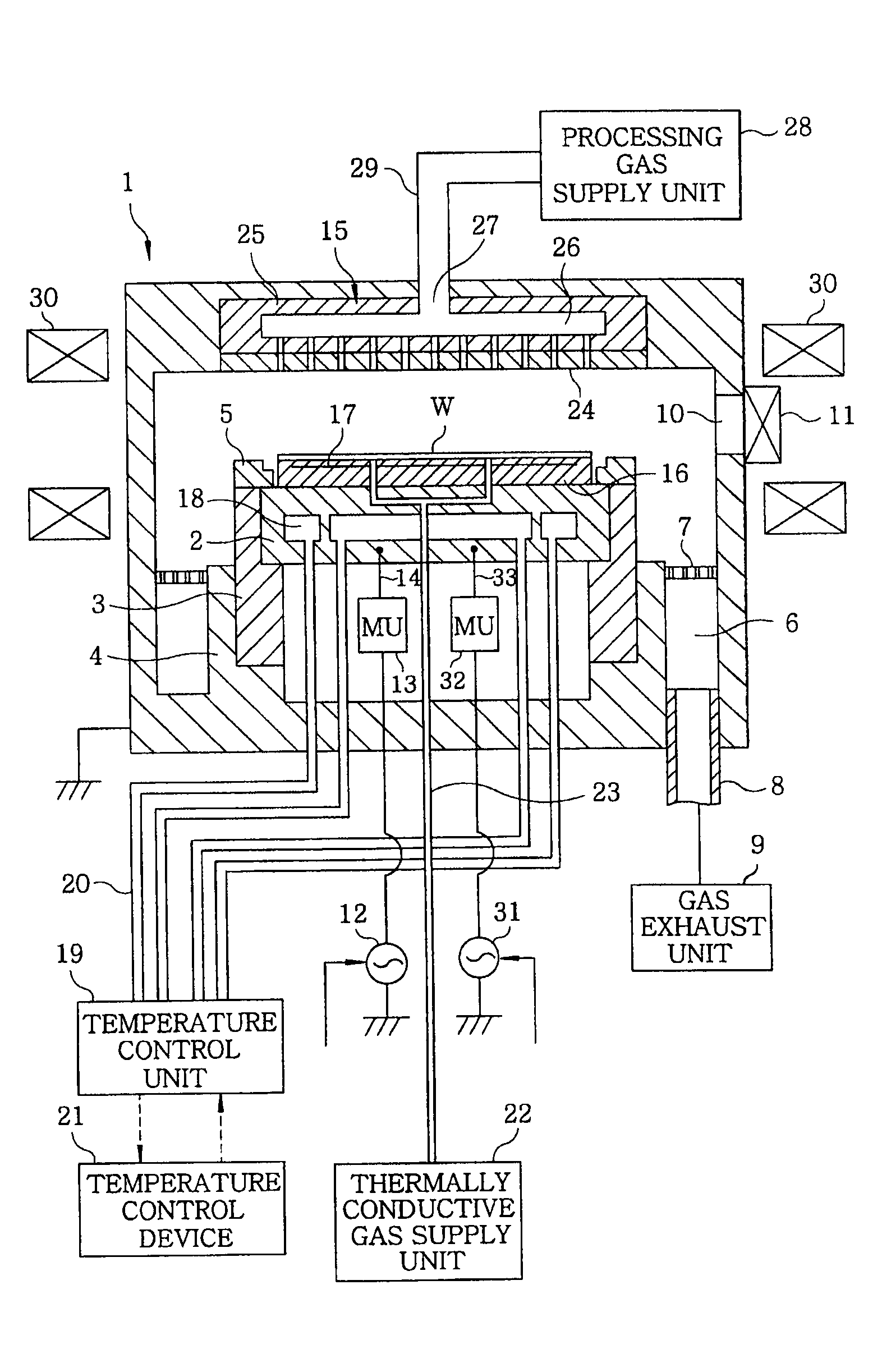
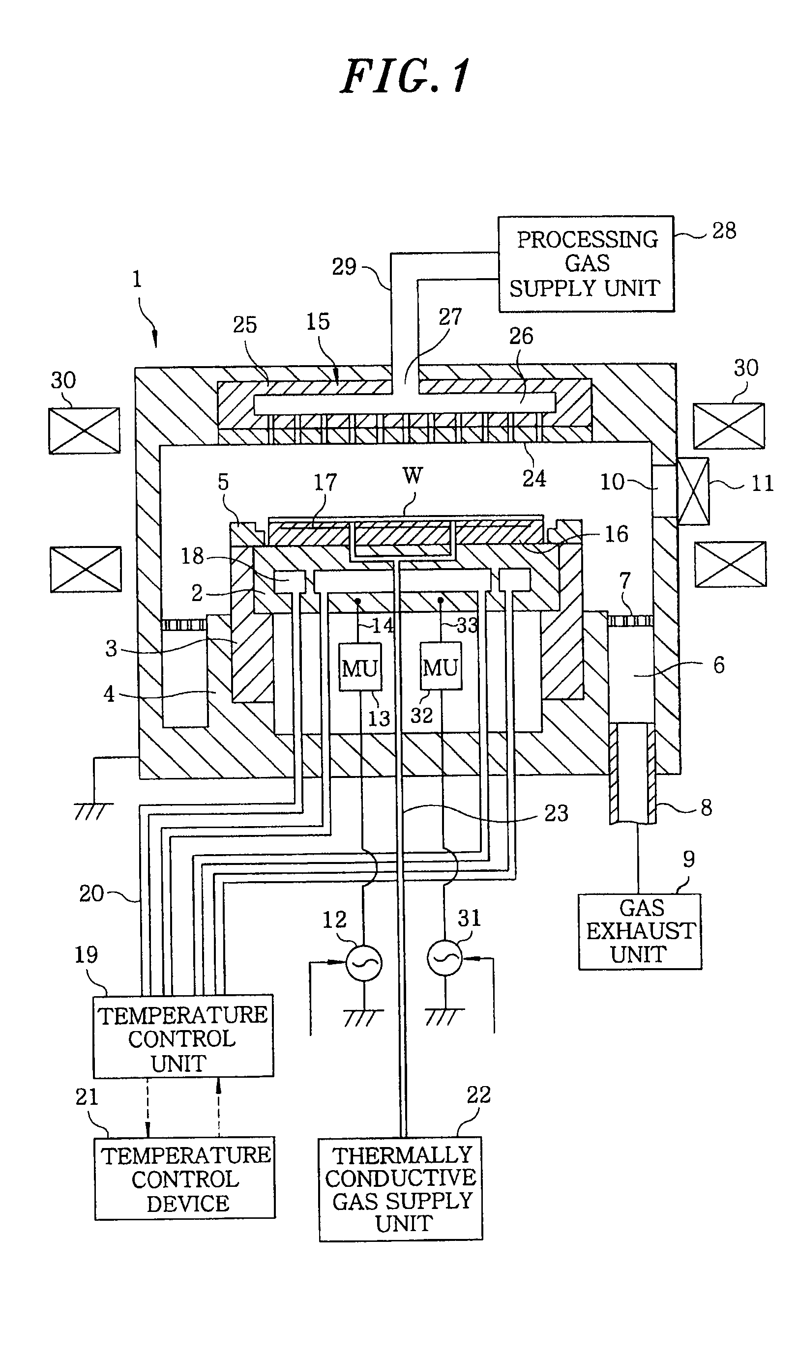
[0040]The embodiments of the present invention will be described with reference to the accompanying drawings which form a part hereof. FIG. 1 schematically shows an entire configuration of a plasma processing apparatus (plasma etching apparatus) used for implementing the present invention. A chamber 1 shown in FIG. 1 is made of, e.g., aluminum, stainless steel or the like, and is formed in a cylindrical shape whose inner space can be airtightly sealed. The chamber 1 is grounded to the earth.

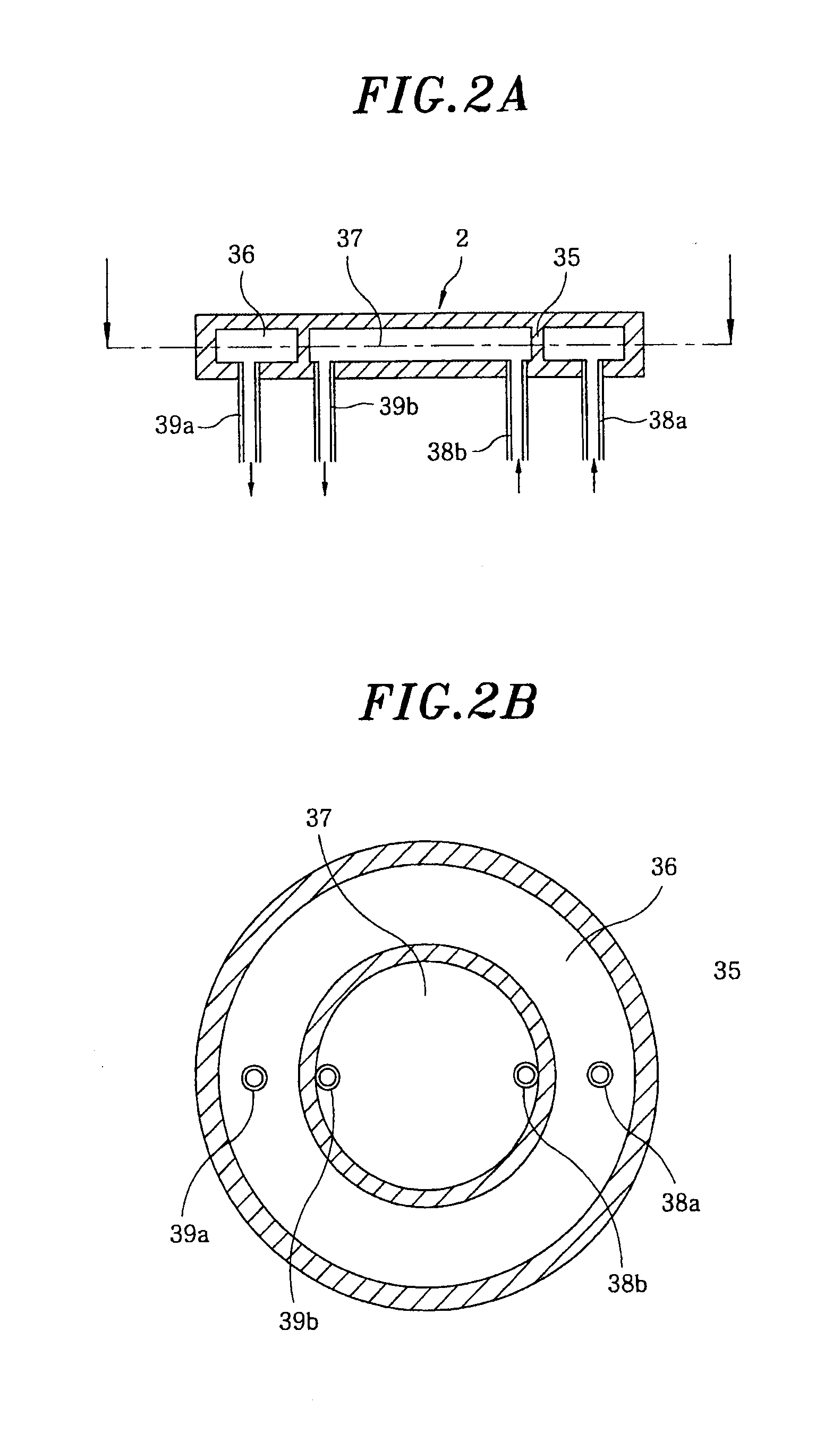
[0041]Provided in the chamber 1 is a mounting table (hereinafter, referred to as a “susceptor”) 2 for mounting thereon a substrate to be processed, e.g., a semiconductor wafer W. A susceptor 2 illustrated in FIG. 1 performs heat exchange while being in contact with the semiconductor wafer W and serves as a heat exchanger plate for controlling a temperature of the semiconductor wafer W. The susceptor 2 is made of a material of high conductivity and high thermal conductivity such as aluminum or the...


PUM

PropertyMeasurementUnit
Temperatureaaaaaaaaaa
Flow rateaaaaaaaaaa

Abstract

A temperature control device for a target substrate includes a mounting table having temperature control members respectively provided in temperature systems to control temperatures of regions of the target substrate to respective predetermined temperature levels; circulation channels through which fluids passing through the temperature control members flow; and heating channels each for flowing therein a heated fluid having a higher temperature compared to the fluids circulating in the circulation channels. The device further includes cooling channels each for flowing therein a cooled fluid having a lower temperature compared to the fluids circulating in the circulation channels; and joining units that join the circulation channels to build the respective temperature control systems, the joining units having flow rate control units that controls flow rate ratios of the fluids supplied from the respective channels to the temperature control members.

Description

FIELD OF THE INVENTION[0001]The present invention relates to a device for controlling a temperature of a semiconductor wafer serving as a substrate; and, more particularly, to a temperature control device for a target substrate which has temperature control members capable of independently controlling respective temperatures of a plurality of regions of a mounting table for mounting thereon the target substrate, a temperature control method and a plasma processing apparatus including same.BACKGROUND OF THE INVENTION[0002]In a plasma processing apparatus for performing plasma etching or the like on a target substrate, the processing is often performed while a temperature of the substrate being changed stepwisely. FIG. 6 is a chart diagram showing a stepwise temperature control in performing processing in a same processing chamber while etching conditions (gas types, temperatures, pressures and the like) being changed. In order to perform the stepwise temperature control, the temperat...

Claims


Application Information

Patent Timeline
IPC IPC(8): G05D23/00G05D11/02
CPCG05D23/1934H01L21/324
Inventor NONAKA, RYOMURAKAMI, KOICHI
Owner TOKYO ELECTRON LTD
Learn More