Digitally controlled three-phase pfc rectifier

a three-phase rectifier and digital control technology, applied in the field of digital control of three-phase power converters, can solve the problems of not being applicable to a three-wire connection only three-wire rectifier, not being available in many practical applications, and not being applicable to a three-wire rectifier with only a three-wire connection (e.g. a delta). achieve the effect of simple and practical method

Active Publication Date: 2009-05-14
DELTA ELECTRONICS INC
View PDF2 Cites 59 Cited by
  • Summary
  • Abstract
  • Description
  • Claims
  • Application Information

AI Technical Summary

Benefits of technology

[0009]The present invention provides a simple and practical method for segment identification in a power converter handling both balanced and unbalanced input voltages. According to one embodiment, segment identification is achieved using three zero-crossing signals derived from line voltage difference signals. A method of the present invention is applicable to a wide range of input-voltage conditions (e.g., the present invention is applicable to both the balanced and unbalanced input voltages without a zero-sequence component), and may be implemented using either digital or analog techniques.

Problems solved by technology

One problem associated with the six-step PFC rectifier relates to segment identification for both balanced and unbalanced input voltages.
However, this technique requires a neutral line, which may not be available in many practical applications.
As a result, while this zero-crossing detection technique is applicable to a three-phase rectifier with a four-wire connection (e.g. a Wayne connection), it is not applicable to a three-phase rectifier with only a three-wire connection (e.g. a Delta connection).
This technique, however, leads to rather complex implementations, because detecting the line frequency and its variations require a phase-locked loop (PLL) circuit.
Furthermore, this technique is generally not applicable to unbalanced input voltages, for which the phase angle between line and phase voltages is not necessarily 30°.
Since the binary input signals are usually obtained by voltage comparators from input voltages that are susceptible to disturbance, the decoder may generate a false switching state as its output.
A false switching state increases switching losses, component stresses and distortions of line current waveforms.
However, it is difficult to design an optimal hysteresis band, because the amplitude of an unexpected input-voltage disturbance is almost impossible to estimate.
Moreover, an excessive hysteresis band may cause an unacceptable phase delay, which causes the line currents to be significantly out of phase with the corresponding input voltages.
Yet another problem relates to current glitches during segment transitions.
However, due to the current loop's limited bandwidth, the duty cycle changes may not be fast enough, thereby creating current transients that are seen as current glitches in the line current waveforms at the instants of segment transitions.
However, the implementation described in the article requires two extra analog electronic switches and a synchronization signal for each of the three current loops, adding extra complexity to an already complex analog controller circuit.

Method used


Image

  • Digitally controlled three-phase pfc rectifier
  • Digitally controlled three-phase pfc rectifier
  • Digitally controlled three-phase pfc rectifier

Examples


Embodiment Construction

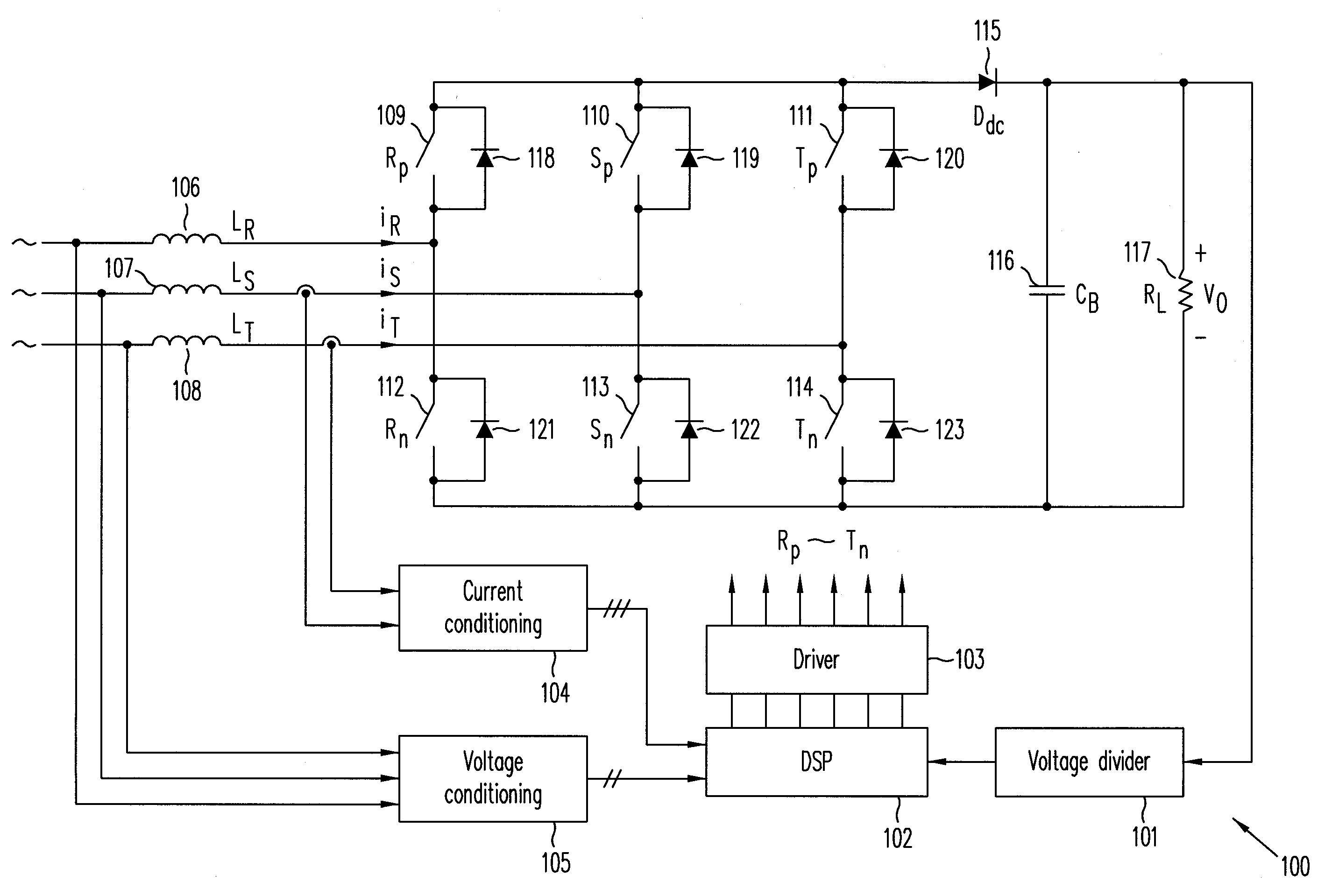
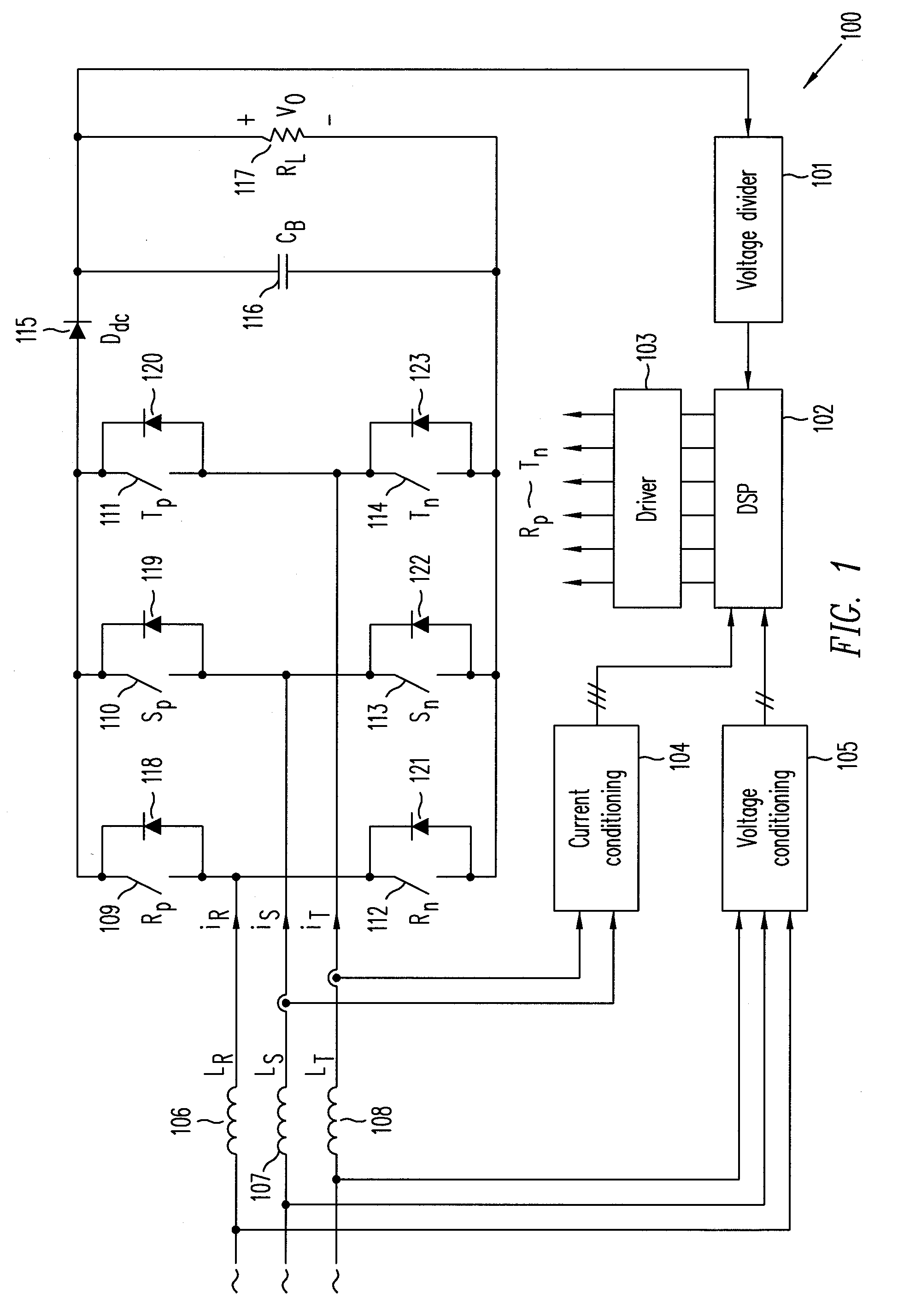
[0027]FIG. 1 is a circuit diagram of digitally controlled three-phase boost PFC rectifier 100 (“PFC rectifier 100”), in accordance with one embodiment of the present invention. As shown in FIG. 1, PFC rectifier 100 includes digital signal processor (DSP) 102 which receives as input signals (a) output voltage V0 from voltage divider 101, (b) the input voltages of PFC rectifier 100 from voltage conditioning circuit 105, and (c) two of the three input currents from current conditioning circuit 104. DSP 102 provides control signals from driver 103 to control or drive switches 109-114 of PFC rectifier 100.

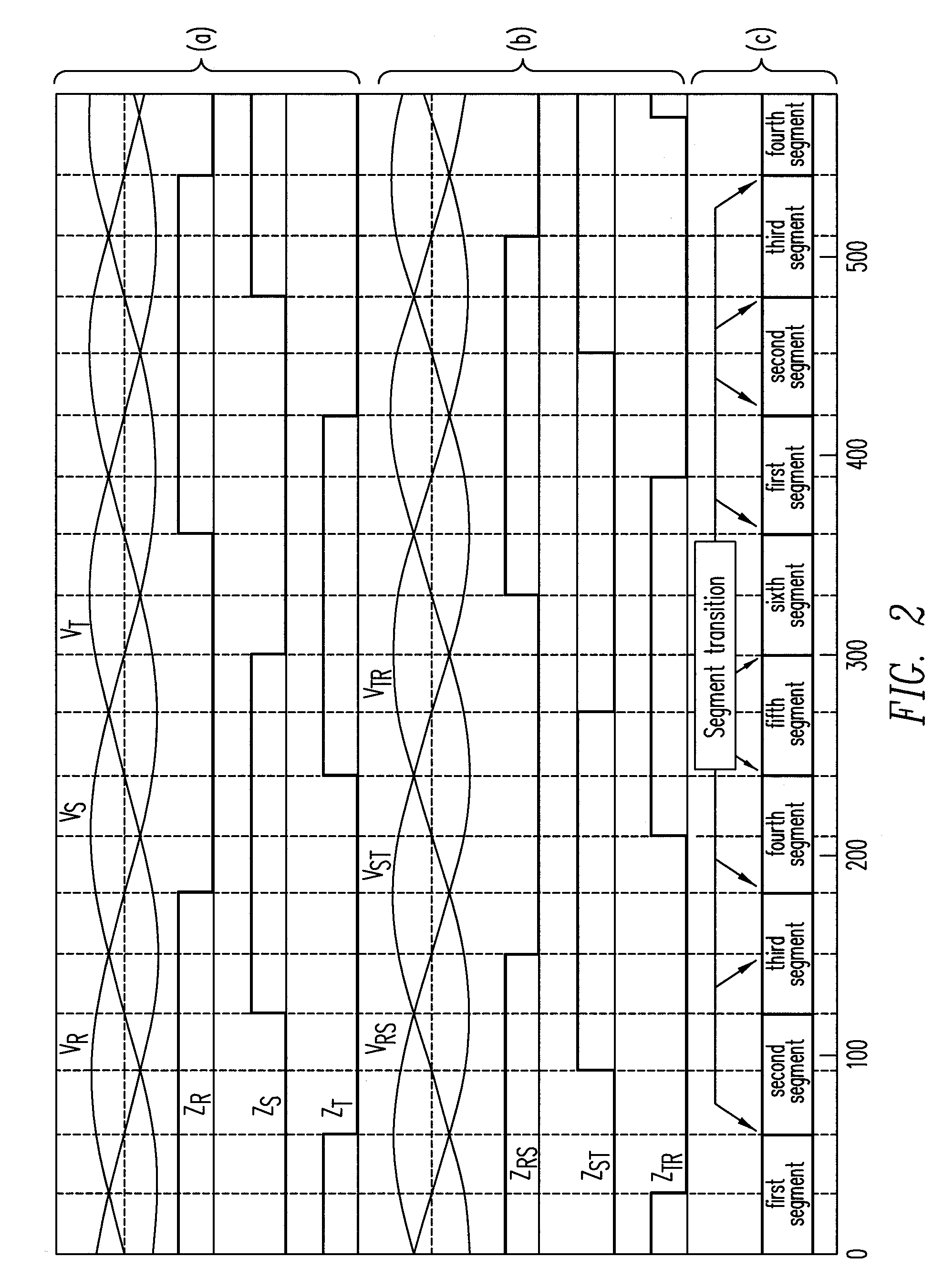
[0028]With balanced three-phase input voltages, PFC rectifier 100 divides the line cycle of the input voltages into six 60° segments. Within each segment, the input phase voltages do not change sign, and the phase voltage with the largest absolute value and a sign opposite those of the other two phase voltages is “disabled,” while the other two phase voltages are “enabled.” During each ...


PUM


Abstract

A robust decoder generates an output state from input signals related to the line-voltage signals of a three-phase power system, using a segment identification method based on zero-crossings derived from line-voltage difference signals. The robust decoder includes a basic decoder that provides a current output state based on the input signals, a state table that provides a presumed previous state based on the current output state of the basic decoder, a binary feed back loop including a state element for storing a previous output state, and a selector for providing the output state based on the stored previous output state and the presumed previous state. The robust decoder may be implemented as hardware or software in a digital power converter. Such a digital power converter may include boost inductors each receiving an input line voltage signal from the three-phase power system to provide phase voltage signals, switches receiving the phase voltage signals to provide an intermediate voltage signal, the plurality of switches each being control by a driving signal, an output circuit coupled to the intermediate voltage signal to provide a rectified output voltage signal for digital power converter, and a digital control circuit receiving the input line voltages and the output voltage signal, the digital control circuit generating the driving signals to control the switches. The switches may be configured according to a state machine.

Description

BACKGROUND OF THE INVENTION[0001]1. Field of Invention[0002]This present invention relates to digital control of three-phase power converters. Specifically, the present invention relates to digital control of three-phase boost power-factor-corrected (PFC) rectifier.[0003]2. Discussion of the Related Art[0004]The six-step, three-phase boost PFC rectifier is widely used in high-power AC-to-DC conversions. Such a PFC rectifier achieves both low total harmonic distortion (THD) in its currents and unity power factor. The six-step operation is based on dividing a line cycle into six segments, with each segment being one of six switch states generated from either line or phase input voltages. In each segment, a specific pair of switches (i.e., two switches affiliated with two corresponding enabled phase voltages) are controlled by pulse width modulation (PWM) to implement single-switch, single-phase boost PFC rectification for each of the two phase voltages. At any given time, a switch sta...

Claims


Application Information

Patent Timeline
Patent Type & Authority Applications(United States)
IPC IPC(8): H02M7/155H02M7/02G06G7/12
CPCY02B70/126H02M1/4233Y02B70/10Y02P80/10
Inventor YE, ZHEN Z.JOVANOVIC, MILAN M.
Owner DELTA ELECTRONICS INC
Why Eureka
Try Eureka