Luminescent solar concentrators

a technology of solar concentrators and solar panels, which is applied in the direction of pv power plants, lighting and heating apparatus, planar/plate-like light guides, etc., can solve the problems of reducing optical efficiency, reducing performance, and lack of impact resistance and flame retardance, so as to achieve the effect of increasing performan

Active Publication Date: 2009-05-21
SHPP GLOBAL TECH BV
View PDF10 Cites 53 Cited by
  • Summary
  • Abstract
  • Description
  • Claims
  • Application Information

AI Technical Summary

Benefits of technology

[0010]There is a need for durable luminescent solar concentrators having

Problems solved by technology

One of the most expensive components of the LSC is the photovoltaic cell (PV cell).
However, a large collection area generally means the photons in the center of the collection area must travel a long distance to the photovoltaic cell.
This reduces optical efficiency as those photons travel through the medium of the collector and are either absorbed or reflected away from a path that eventually arrives at the edge.
For example, for forming the collector, the

Method used


Image

  • Luminescent solar concentrators
  • Luminescent solar concentrators
  • Luminescent solar concentrators

Examples


example 1

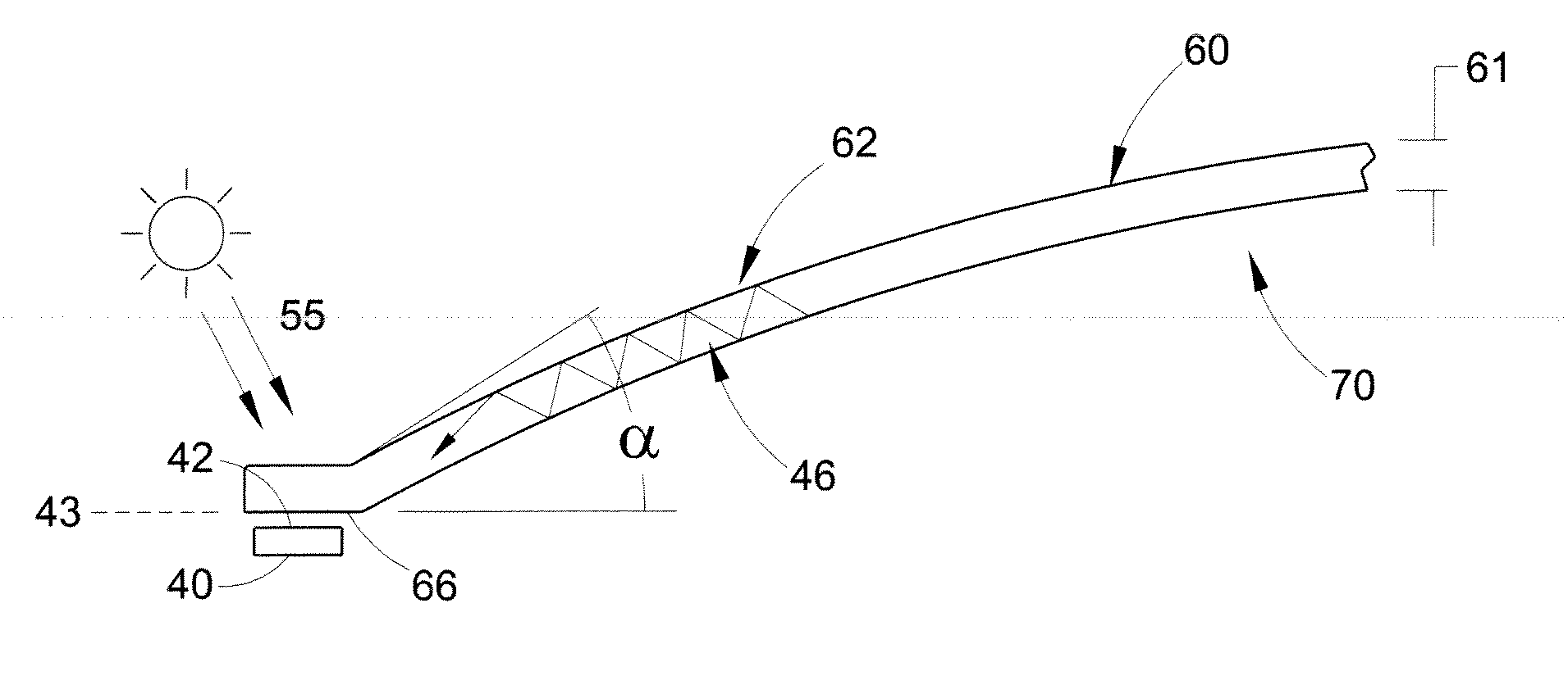
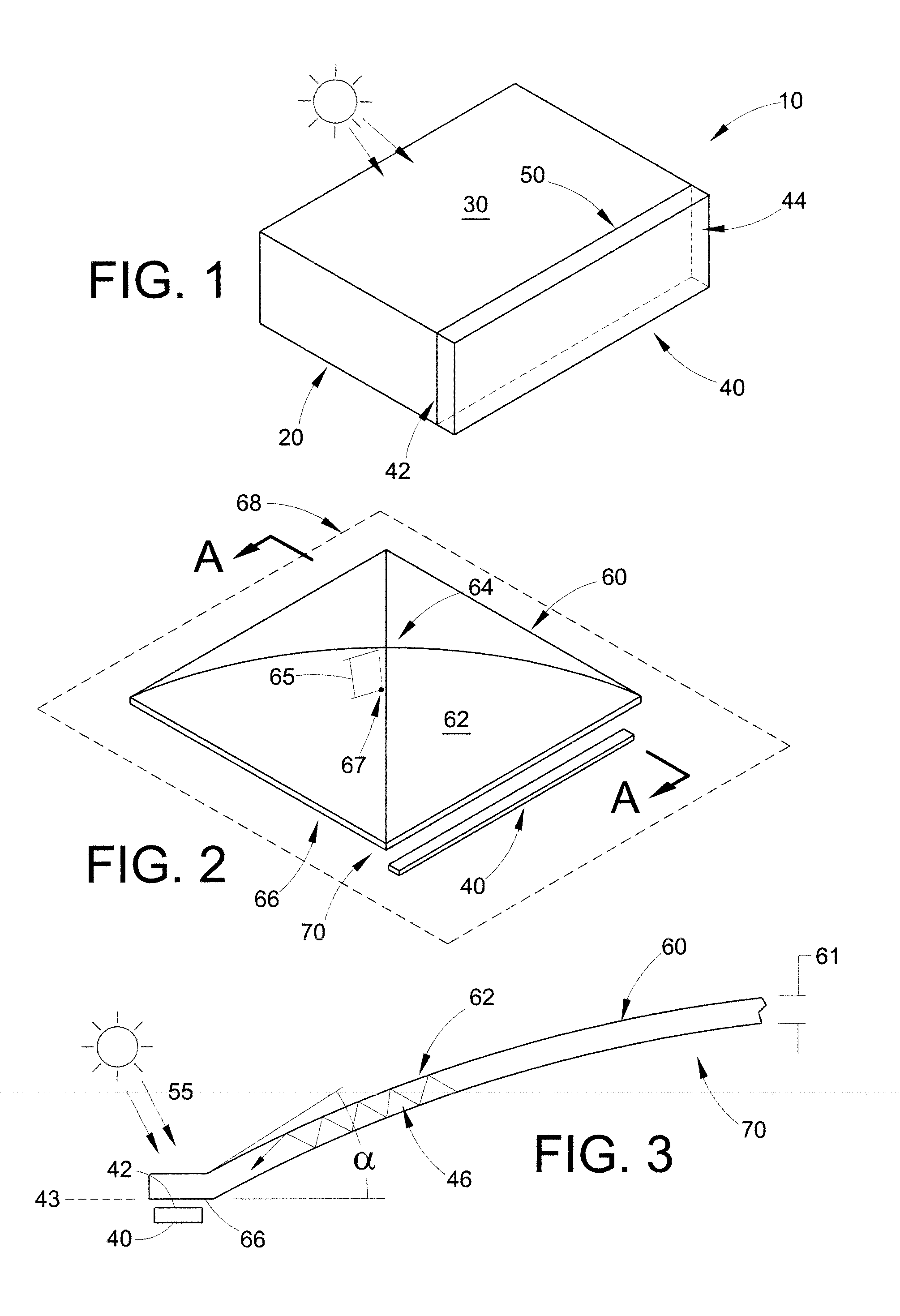
[0112]A luminescent solar concentrator module was made consisting of a primary waveguide, a back sheet, four photovoltaic cells, wiring, a junction box, gel, and adhesive. The design was optimized to maximize the total amount of light reaching a photovoltaic cell. Both the primary waveguide and the back sheet were extruded, then thermoformed into the desired shape, using methods known in the art.

[0113]The primary waveguide was a clear transparent polycarbonate (LEXAN® polycarbonate, available from SABIC Innovative Plastics) with a luminescent dye (a red Lumogen® dye) and a UV stabilization coating. The back sheet was a matte white polycarbonate. Photovoltaic cells were cut to be the same size as the emitting edges of the primary waveguide.

[0114]The photovoltaic cells were arranged on the back sheet, with distance holders underneath placed so that there was a gap of about 1.5 mm between the back sheet and the cells. Wires were then glued onto the cells while ensuring the wires did no...

example 2

[0118]It was expected that losses in optical efficiency would result from surface defects and contamination since total internal reflecting conditions are not optimal. It was thus expected that the type of adhesive used to join the primary waveguide and back sheet together would cause large losses in edge emission.

[0119]A computer simulation was performed wherein the adhesive was a 20 mm broad strip of black glue. Without the black glue, the edge emission was 3000 W / m2 and 2.99 W. With the black glue, the emission was 459 W / m2 and 0.45 W. Thus, the use of black glue reduced edge emission by 85%.

[0120]Next, a square unit was used to measure the loss due to acrylic paste. First, the edge emission was measured for each edge of the unit without any acrylic paste joining the primary waveguide and back sheet. Next, a 7 mm broad strip of acrylic paste was applied to all four sides of the primary waveguide and emission of each edge was measured. Additional acrylic paste was then added to fo...

example 3

[0121]Three different adhesives were tested at three different thicknesses to determine their effect on the efficiency of a luminescent solar concentrator. The three adhesives were Loctite® 3321 resin (an acrylic-based UV curable resin), RTV 6166 resin (a 2-component silicone resin from Momentive Performance Materials), and 3M® VHB-4910 optical tape. The three thicknesses were 0.5 mm, 1 mm, and 2 mm. The efficiencies were tested before the adhesive was added, and after the adhesive was added. Results are shown in Table 2.

TABLE 2EfficiencyEfficiencyThicknessBeforeAfterEfficiencyAdhesive(mm)Adhesive (%)Adhesive (%)Gain (%)optical tape0.511.1711.220.05optical tape19.7310.690.96optical tape210.7311.781.05Silicone resin0.59.6210.741.12Silicone resin19.1810.631.45Silicone resin29.7011.852.15acrylic resin0.58.9412.233.29acrylic resin19.3312.122.79acrylic resin28.8311.272.44

[0122]The cell efficiency increased after application of adhesive. The Loctite® 3321 resin provided the best increase ...


PUM


Abstract

A luminescent solar concentrator comprises a primary waveguide and at least one photovoltaic cell. The primary waveguide has a curved surface which concentrates light on a perimeter. The photovoltaic cell is oriented at the perimeter so that it can both receive the concentrated light and receive direct light as well. A back sheet may be provided that provides structural support and protection. The perimeter may have the shape of a polygon where a photovoltaic cell is oriented along each edge. Modules and arrays of such units are also disclosed.

Description

CROSS-REFERENCE TO RELATED APPLICATIONS[0001]This application claims priority to U.S. Provisional Patent Application Ser. No. 60 / 989,229, filed on Nov. 20, 2007. This application is related to U.S. patent application Ser. No. 12 / 194,008, titled LUMINESCENT SOLAR COLLECTOR, and filed Aug. 19, 2008; and to U.S. patent application Ser. No. 12 / 194,199, titled LUMINESCENT SOLAR COLLECTOR, and also filed Aug. 19, 2008. These three applications are hereby fully incorporated by reference herein.BACKGROUND[0002]The present disclosure relates generally to luminescent solar concentrators, including those having geometric and other improvements that provide increased and / or uniform output. It also relates to methods of manufacturing and utilizing such concentrators.[0003]Luminescent solar concentrators, also known as luminescent solar collectors or LSCs, are beneficial for capturing solar energy (direct and diffuse sunlight) for use. The LSCs collect incident radiation over a large surface area...

Claims


Application Information

Patent Timeline
IPC IPC(8): H01L31/042H01L31/00F24S23/00
CPCF24J2/065F24J2/067F24J2002/003H01L31/0547H01L31/055Y02E10/52H01L31/0543G02B6/0011F24S23/11F24S23/12F24S2023/88
Inventor BROUNNE, MARCELWANG, HUASHAN
Owner SHPP GLOBAL TECH BV
Why Eureka
Try Eureka