
Green joining ceramics

Inactive Publication Date: 2009-05-21
GENERAL ELECTRIC CO
View PDF11 Cites 13 Cited by
  • Summary
  • Abstract
  • Description
  • Claims
  • Application Information

AI Technical Summary

Benefits of technology

[0011]Quickly bonding the components to one another and cooling the bond quickly is important so that the individual components do not change shape while at an elevated temperature where the components are softer.
[0018]The manufacturing process is substantially simplified. Both the total time and number of steps are reduced.
[0019]The process is not limited to cylindrical shapes or hollow tubing and thus advantageously expands the possibility for a wide range of designs and complex geometries that cannot be molded as single pieces.
[0020]The process is also attractive because it is inexpensive, uses relatively safe materials (water), and can be performed in high volume.
[0021]The dimensional accuracy of the finished parts and the repeatability of the process also appear to be superior to other approaches.

Problems solved by technology

These cracks appear to develop during the debindering cycle in the furnace, and it is believed that the cracks are caused at least in part from an interference fit and the resulting forces that are transferred from one component to the other.
Thus, although the known process is successful in mechanically bonding the components together, any cracks are an undesired limitation in forming a hermetic bond between the components that is critical to lamp functionality.
This compression and stretching may occur multiple times, and even though the completed arc tube allegedly achieves desired performance characteristics, a visible seam remains after sintering.
Excessive handling of bonded green components result in cracks and / or undesirably subject the joined component to forces and stresses that may lead to cracks in the final part.

Method used


Image

  • Green joining ceramics
  • Green joining ceramics
  • Green joining ceramics

Examples


Embodiment Construction

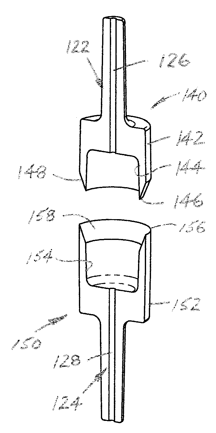
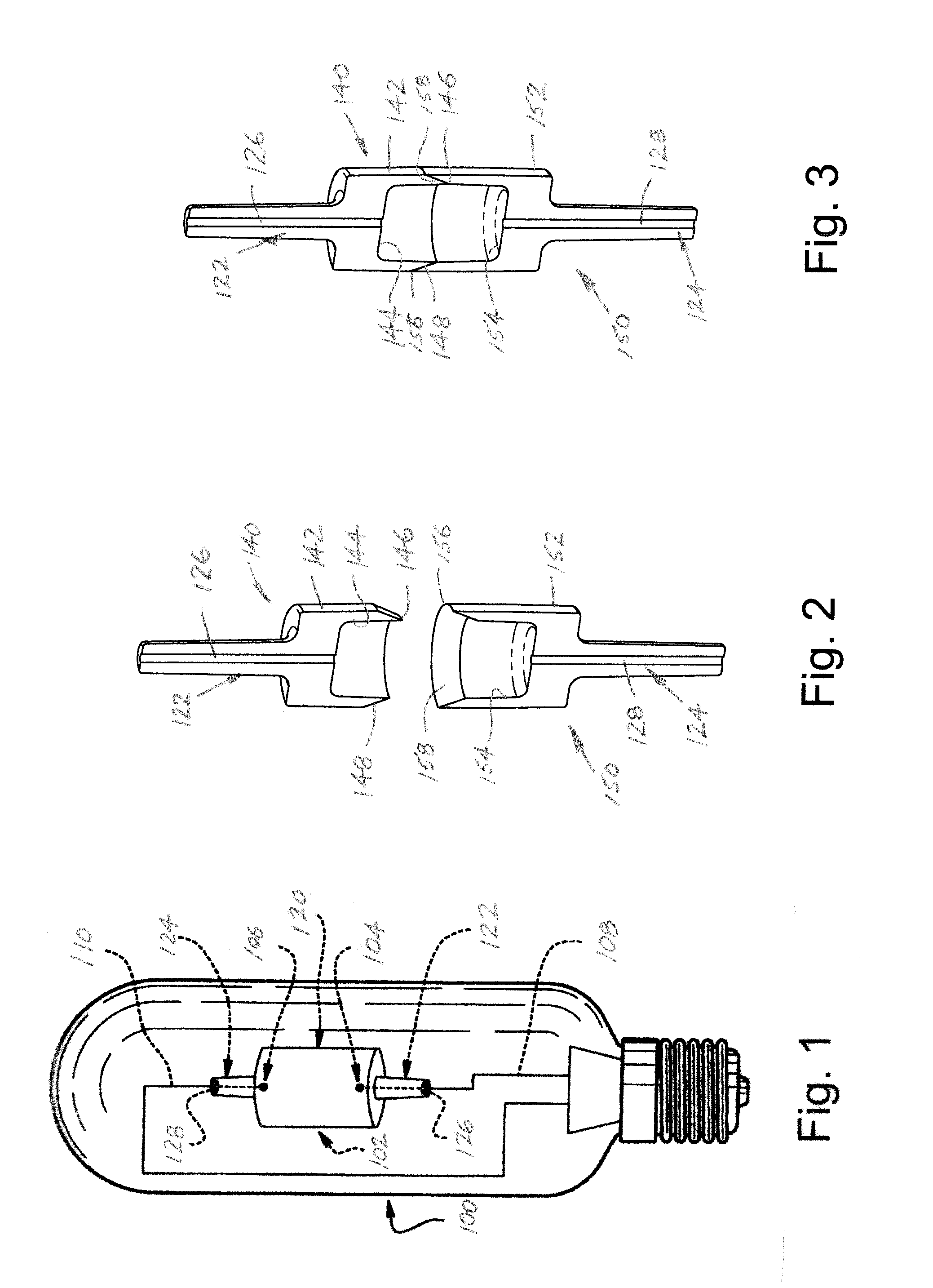
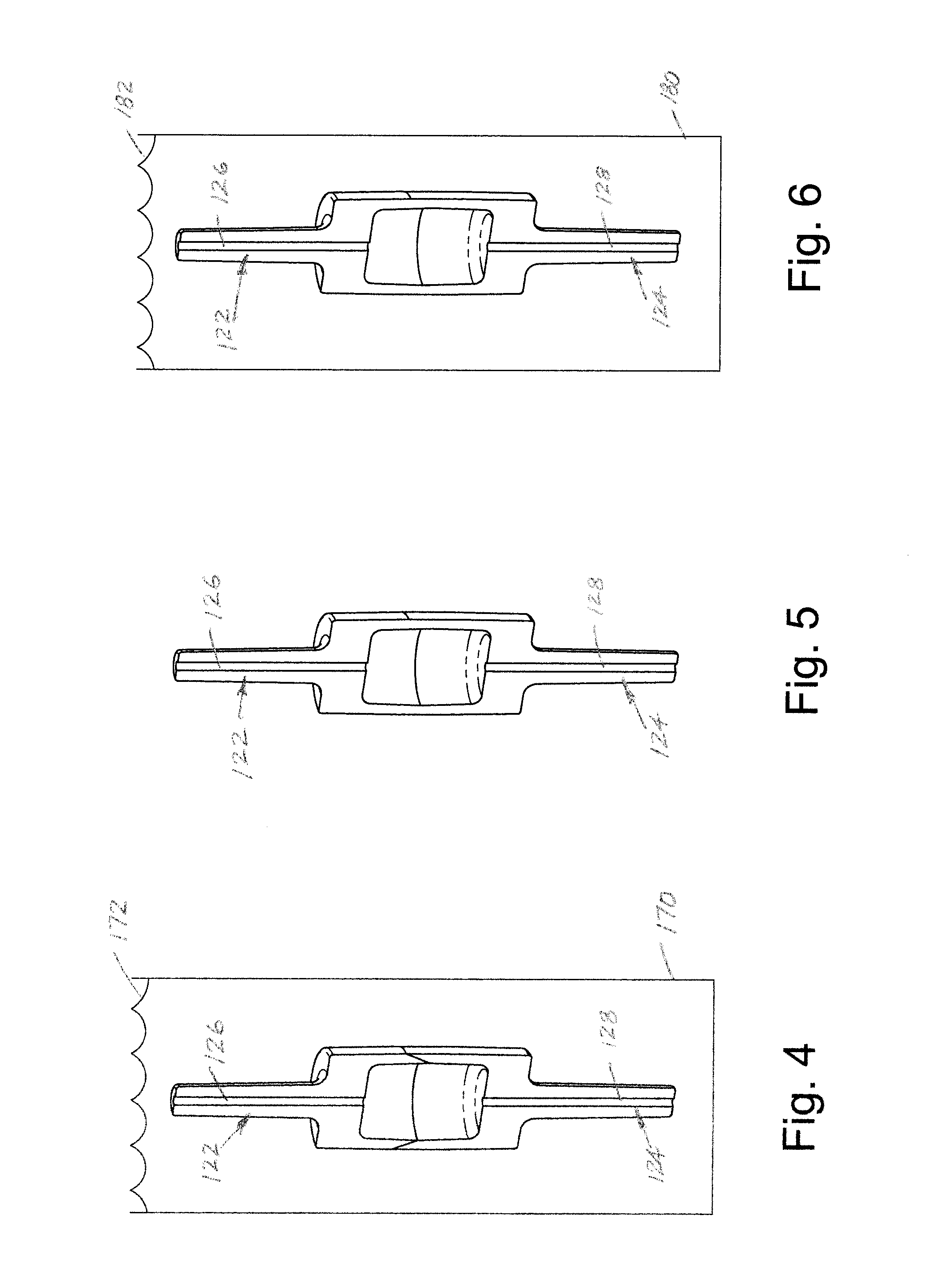
[0033]A standard construction for ceramic metal halide (CMH) lamps includes a three-piece ceramic component where an extruded body tube is capped on either end by an injection-molded part. A required hermetic seal is obtained between the molded leg portions and the central tubular portion, particularly when debindering and sintering have been completed. For example, the arc tube preferably comprises alumina (Al2O3) having a purity of about 99.98% and a surface area of about 2-10 m2 / g before sintering. The alumina powder can be doped with magnesia to inhibit grain growth, for example in an amount equal to about 0.03-0.2%, preferably about 0.05% by weight of the alumina. Other ceramic materials which may be used include non-reactive refractory oxides and oxynitrides, such as yttrium oxide, lutetium oxide, and hafnium oxide, and their solid solutions and compounds with alumina, such as yttrium-aluminum-garnet and alumina oxynitride. Binders which may be used individually or in combinat...


PUM

PropertyMeasurementUnit
Timeaaaaaaaaaa
Timeaaaaaaaaaa
Temperatureaaaaaaaaaa

Abstract

A method of green joining ceramic components is disclosed, particularly for use in forming a discharge body for a ceramic metal halide lamp. The process includes providing a first green ceramic component having a male joining surface, and providing a second green ceramic component having a female joining surface dimensioned to matingly receive the first component. The first and second green ceramic components are assembled along the joining surfaces, the assembled components are uniformly heated to join the first and second components. The joined components are next cooled in a cooling bath that uniformly cools the joined components. Thereafter, the joined green part may be inserted in the furnace for debindering and sintering.

Description

BACKGROUND OF THE INVENTION[0001]This disclosure relates to green joining of ceramic components, and more particularly, is directed to a method of joining green ceramic components of the type used in a high intensity discharge (HID) lamp application. However, this application should not be limited to that particular application and may find application and benefit in related environments and uses.[0002]A need exists for a simple and inexpensive manner of bonding ceramic components together. It is known by way of other disclosures, to mechanically assemble the components or parts, then place the assembled components into a debindering furnace for removal of the wax, a typical binder, so that exposure over a preselected time and temperature causes the components to bond. A portion of these components experience what appear to be hoop-stress cracks extending generally parallel to an axis of the assembled components. These cracks appear to develop during the debindering cycle in the fur...

Claims


Application Information

Patent Timeline
IPC IPC(8): H01J61/30B29C70/28H01J9/24C04B37/00
CPCH01J9/247H01J61/302H01J61/827Y10T156/10C04B2237/343C04B2237/76C04B37/001
Inventor KUENZLER, GLENN H.BOYLE, THOMAS J.YEE, MICHAEL VINCENTDANISON, BRIAN
Owner GENERAL ELECTRIC CO
Learn More