
Thermoelectric Conversion Module

Inactive Publication Date: 2009-05-28
UNIVERSAL ENTERTAINMENT CORP
View PDF7 Cites 68 Cited by
  • Summary
  • Abstract
  • Description
  • Claims
  • Application Information

AI Technical Summary

Benefits of technology

[0011]The present invention has been made to solve the foregoing problems, and an object of the present invention is to provide a thermoelectric conversion module enabling cost reduction by reducing the number of parts, making the assembly procedure simpler, reducing time and work required for assembly, and so on.Means for Solving the Problems
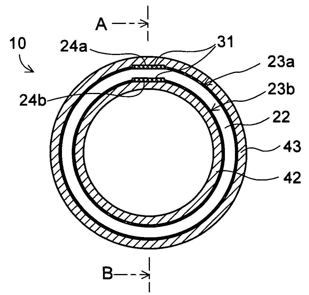
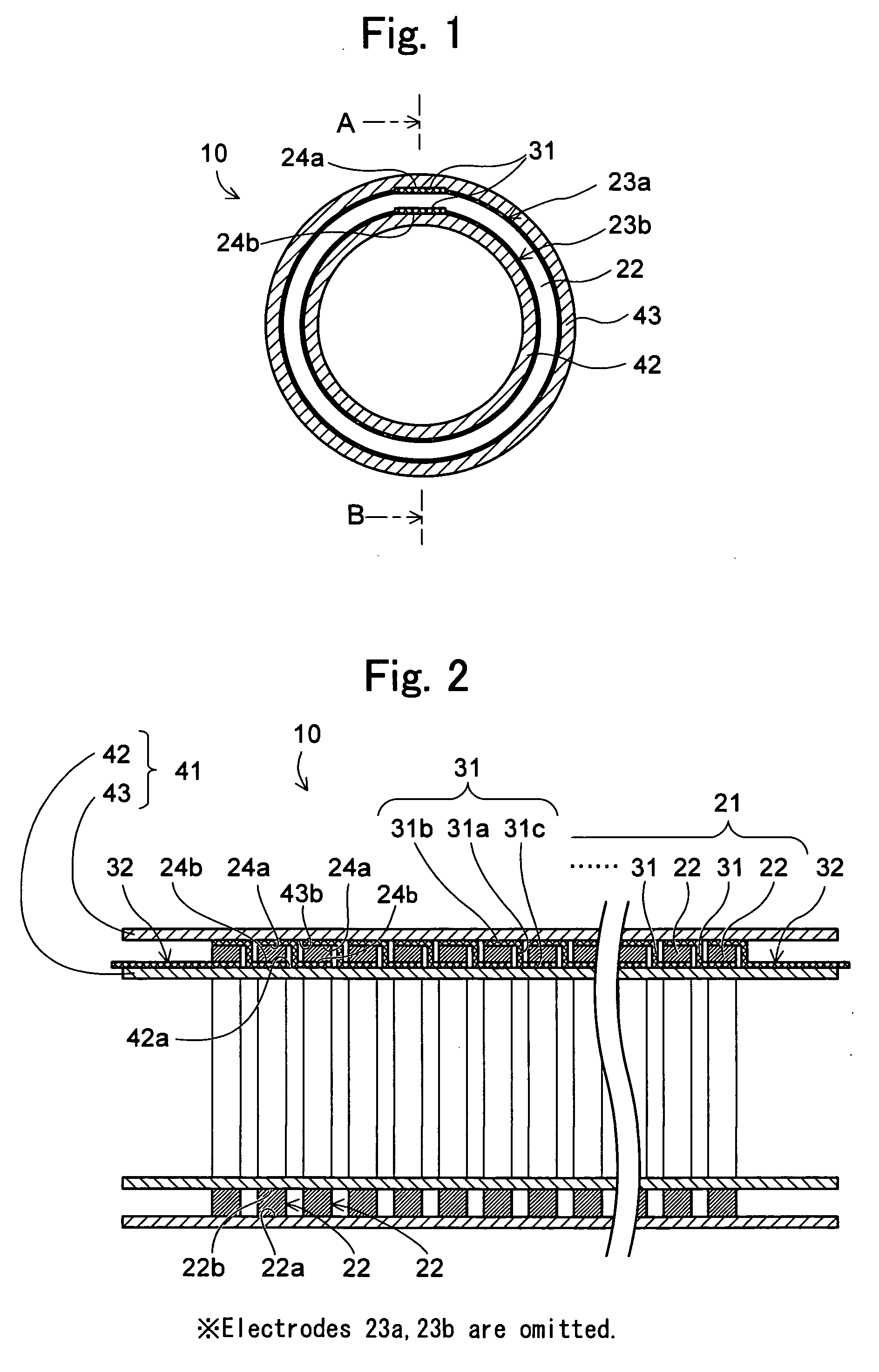
[0014]A In accordance with the invention in the first aspect, a doubled cylindrical support unit consisting of an electrically insulated inner tube that internally touches the tubular element unit and whose outer circumference surface supports the tubular element unit and an electrically insulated outer tube that externally touches the tubular element unit and whose inner circumference surface supports the tubular element unit is provided. Accordingly, the thermoelectric conversion module according to the present invention can be assembled easily in comparison to a conventional thermoelectric conversion module in which a plurality of thermoelectric elements needed to be arranged in a rotation symmetric form between an inner tube and an outer tube since it has a simple structure in which the tubular element unit is supported by the inner tube and the outer tube. Thus, it is possible to reduce time and work required for assembly and enable cost reduction.
[0017]The above inner tube and outer tube may have a function of limiting movement of fluid substances such as gas, liquid, particles, etc. residing on the inner circumference surface side and outer circumference surface side of the above thermoelectric conversion module. Also, the above inner tube and outer tube can have a function of making the temperature of the inner circumference surface electrode and the outer circumference surface electrode of each thermoelectric element in the above thermoelectric conversion module relatively constant within each electrode. Further, the above inner tube and outer tube can have a structure that enables efficient heat transfer from various kinds of fluid substances such as gas, liquid, particles, etc. moving nearby. For example, macro- or micro-fins or the likes can be attached.
[0018]Also, other than the above inner tube and outer tube, a heat blocking member having the above functions can be provided. This heat blocking member can include a heat blocking body such as, for example, the above inner tube and / or outer tube. The heat blocking body can include, for example, an insulated ring body to be inserted between the plurality of ring-like thermoelectric elements. Such a ring body can electrically insulate respective ring-like thermoelectric elements in an axis direction along the center axis of the plurality of ring-like thermoelectric elements. Such a ring body can maintain a mutual appropriate space between the plurality of ring-like thermoelectric elements and can function as a structure auxiliary member that can maintain the structure of the entire thermoelectric conversion module.
[0021]In accordance with the second and the third aspects of the present invention, the plurality of ring-like thermoelectric elements have been obtained by processing the sintered body made of entirely the same kind of components. Thus, the thermoelectric conversion module is assembled using the thermoelectric elements obtained by processing the sintered body made of the same kind of components. Accordingly, since it is not necessary to check whether or not the arranging order is correct in comparison to a conventional case in which two kinds of different thermoelectric elements are arranged alternately to assemble a thermoelectric conversion module, it is possible to reduce time and work required for assembly. Also, according to the present invention, the thermoelectric elements of the same kind only need to be purchased, and thus the purchase unit cost can be lowered more than in the case of purchasing two kinds of different thermoelectric elements as in the conventional case, which enables cost reduction.
[0024]According to the present invention, a doubled cylindrical support unit consisting of an electrically insulated inner tube that internally touches the tubular element unit and whose outer circumference surface supports the tubular element unit and an electrically insulated outer tube that externally touches the tubular element unit and whose inner circumference surface supports the tubular element unit is provided. Accordingly, the thermoelectric conversion module according to the present invention can be assembled easily in comparison to a conventional thermoelectric conversion module in which a plurality of thermoelectric elements needed to be arranged in a rotation symmetric form between an inner tube and an outer tube since it has a simple structure in which the tubular element unit is supported by the inner tube and the outer tube. Thus, it is possible to reduce time and work required for assembly and enable cost reduction.

Problems solved by technology

However, the thermoelectric conversion by a single pi-type element cannot exert practical electricity due to insufficient energy output.
In such a manner, the conventional flat-plate structured module needed to be attached to the fluid channel by using the fixing member and the screws, and as a result, an electric generating system using the conventional flat-plate structured module had a complicated structure.

Method used


Image

  • Thermoelectric Conversion Module
  • Thermoelectric Conversion Module
  • Thermoelectric Conversion Module

Examples


embodiment

[0060]A method for preparing the ring-like thermoelectric element is explained with reference to FIGS. 4A to 4C. FIG. 4A is a perspective view showing a Ca0.95Y0.05MnO3 ring-like sintered body 51, FIG. 4B is a front view of the ring-like thermoelectric element 22, and FIG. 4C is a perspective view of the ring-like thermoelectric element 22 whose outer circumference surface 22a and inner circumference surface 22b have been covered approximately entirely with the electrodes 23a, 23b. It is noted that some numerals are omitted in FIGS. 4A and 4C.

[0061]Calcium carbonate, manganese carbonate and yttrium oxide were weighed so that Ca / Mn / Y=0.95 / 1.0 / 0.05 and underwent wet blending in a ball mill for 18 hours. Thereafter, the wet material was filtered, dried, and calcined in the air at 1000 degrees C for 10 hours. The calcined powder obtained was crushed and then molded by a uniaxial press at 1 t / cm2 pressure using a ring-like die. This was sintered in the air at 1150 degrees C. for 5 hours ...


PUM


Abstract

To provide a thermoelectric conversion module enabling cost reduction by reducing time and work required for assembly, and so on. A thermoelectric conversion module 10 comprises a tubular element unit 21 having a plurality of ring-like thermoelectric elements 22 coaxially arranged with air as an insulator sandwiched inbetween, wherein the ring-like thermoelectric element 22 is covered approximately entirely with electrodes 23a, 23b at its outer circumference surface 22a and inner circumference surface 22b, respectively, and generates electricity by temperature difference between the outer circumference surface 22a and the inner circumference surface 22b, a lead wire 31 electrically connecting the electrode 23a covered on the outer circumference surface 22a of one ring-like thermoelectric element 22 among the plurality of ring-like thermoelectric elements 22 to the electrode 23b covered on the inner circumference surface 22b of another ring-like thermoelectric element 22 adjacent to this one ring-like thermoelectric element 22, and a doubled cylindrical support unit 41 consisting of a SUS tube 42 whose outer circumference surface 42a supports the tubular element unit 21 and a SUS tube 43 whose inner circumference surface 43b supports the tubular element unit 21.

Description

TECHNICAL FIELD[0001]The present invention relates to a thermoelectric conversion module, and relates to a thermoelectric conversion module comprising a large number of thermoelectric elements.BACKGROUND ART[0002]Thermoelectric conversion means the conversion of thermal energy to electric energy with use of the Peltier effect or the Seebeck effect. By utilizing the thermoelectric conversion, electricity is taken out from heat flow using the Seebeck effect, or electric current is applied to a material using the Peltier effect, to be able to bring about an endothermic phenomenon or an exothermic phenomenon. Also, the thermoelectric conversion is characterized by no generation of excessive waste at the time of energy conversion due to direct conversion, ability to make efficient use of exhaust heat, maintenance free due to no provision of movable parts such as a motor and a turbine, and so on, and thus attracts attention as a technique for high-efficiency use of energy.[0003]The thermo...

Claims


Application Information

Patent Timeline
IPC IPC(8): H01L35/02H01L35/00
CPCH01L35/22H02N11/002H01L35/32H10N10/855H10N10/17H10N10/00
Inventor TAKAHASHI, KOH
Owner UNIVERSAL ENTERTAINMENT CORP
Learn More