
Method for manufacturing heat resisting member applicable to an exhaust gas guide assembly with improved heat resistance for VGS turbocharger

Inactive Publication Date: 2009-06-11
OHISHI SHINJIRO +1
View PDF8 Cites 1 Cited by
  • Summary
  • Abstract
  • Description
  • Claims
  • Application Information

AI Technical Summary

Benefits of technology

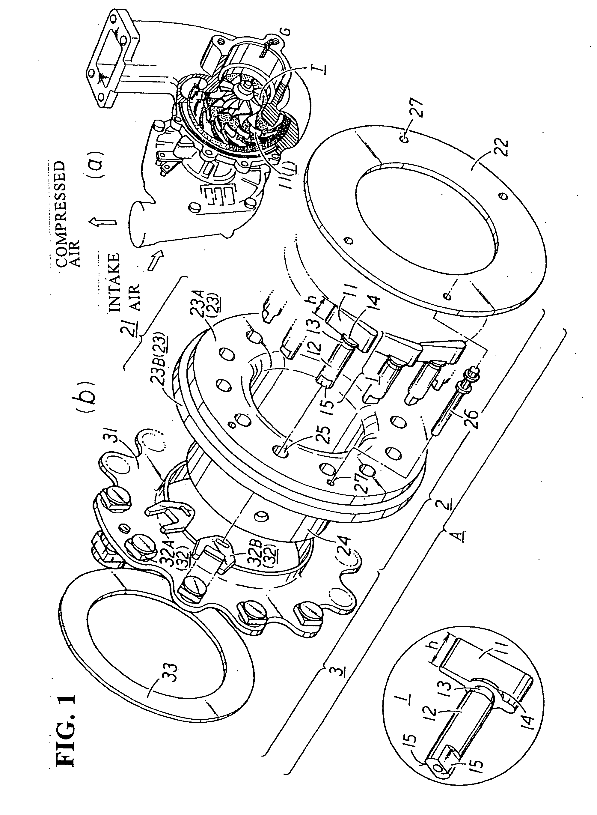
[0009]An exhaust gas guide assembly, with an improved heat resistance, for a VGS turbocharger includes adjustable blades for suitably controlling the flow rate of exhaust gas discharged from an engine to rotate an exhaust turbine wheel; a turbine frame which rotatably supports the adjustable blades at the outside of an outer periphery of the turbine wheel; and an adjusting mechanism for suitably rotating the adjustable blades to control the flow rate of the exhaust gas. The flow of the exhaust gas at a low flow rate is throttled by the adjustable blades to increase the velocity of the exhaust gas so that a high output power is obtained at low rotational speeds. The assembly is characterized in that a heat resisting metal member constituting the exhaust gas guide assembly has a cleanliness level which is set to be not more than 0.1% in the area ratio of nonmetallic inclusions.

Problems solved by technology

The turbocharger, when the engine is running at a low rotational speed, can not avoid giving a slow-moving feeling caused by the reduced flow rate of the exhaust gas and continued until the exhaust turbine runs efficiently, and necessitating a subsequent time or a so-called turbo-lag before the turbine rapidly reaches the full-running state.
Furthermore, in the case of a diesel engine which runs inherently at low rotational speeds, there is a disadvantage that it is difficult to produce an effect of the turbocharger.
However, since the assembly is used under very severe conditions, its life or durability has a certain limit.
However, it is very difficult to obtain a shaped material having a near-net shape for the adjustable blade in a conventional precision casting method or metal injection molding method, and such current techniques have not reached a stage where adjustable blades can be actually mass-produced at a stable and high level.

Method used


Image

  • Method for manufacturing heat resisting member applicable to an exhaust gas guide assembly with improved heat resistance for VGS turbocharger
  • Method for manufacturing heat resisting member applicable to an exhaust gas guide assembly with improved heat resistance for VGS turbocharger
  • Method for manufacturing heat resisting member applicable to an exhaust gas guide assembly with improved heat resistance for VGS turbocharger

Examples


embodiment 1

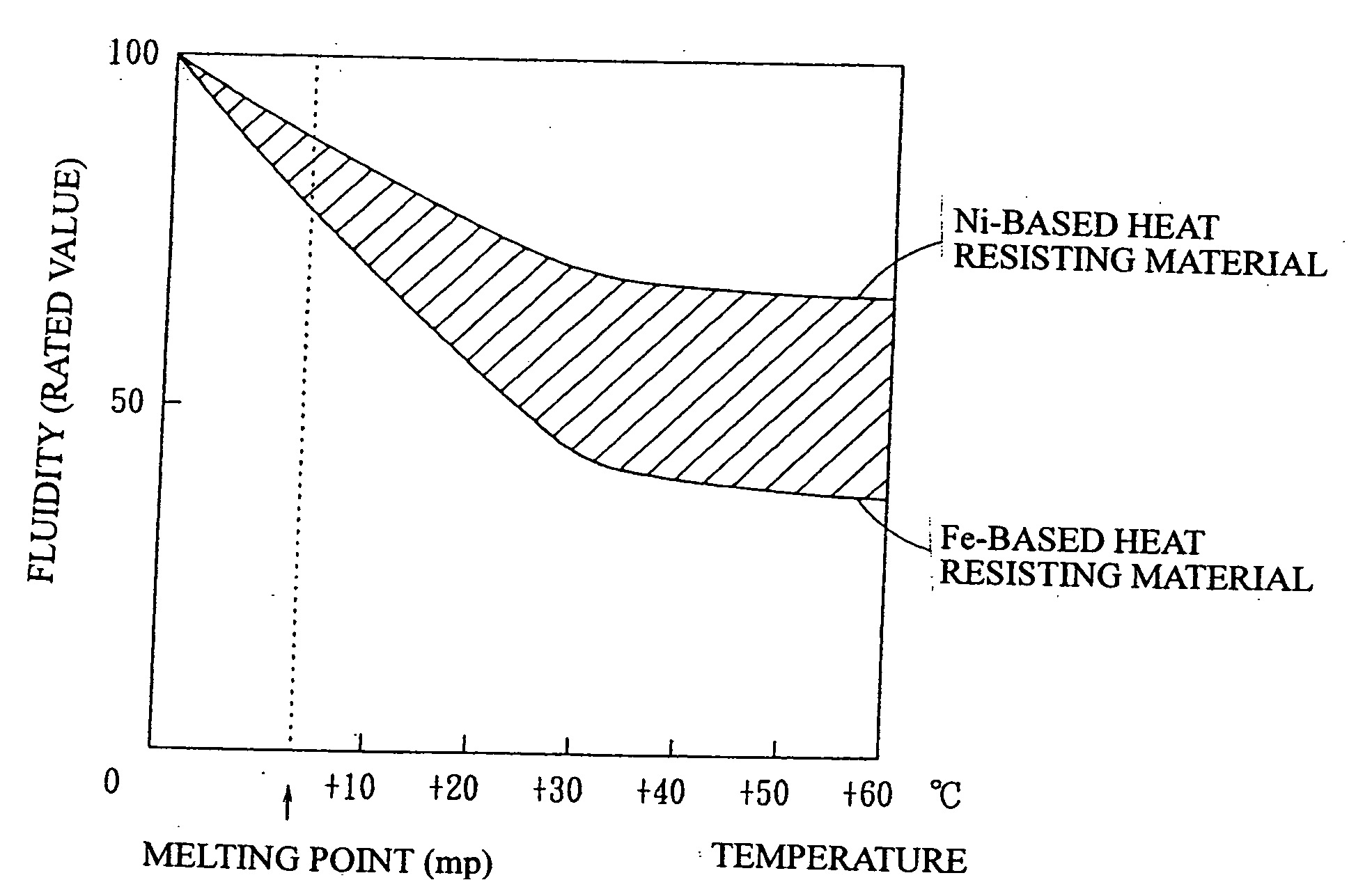
[0086]Embodiment 1 is an embodiment in which the presence of nonmetallic matter present in a heat resisting metal member is decreased and the size of nonmetallic matter is reduced. For this purpose, a method or process, such as calcium injection, a heating pressurization treatment, a pure oxygen blowing refining treatment or the like, is applied to the heat resisting metal member. More specifically, the manufacturing procedure is as follows.

(i) Decrease of Nonmetallic Inclusions in the Heat Resisting Metal Member

[0087]Calcium injection during a refining process decreases generation of nonmetallic inclusions, i.e. oxides (type B and type C inclusions) as well as sulfides (type A inclusions) by discharging sulfur, silicon, aluminum and the like as calcium compounds. Furthermore, by a pure oxygen blowing refining treatment, nonmetallic inclusions of type B and type C are decreased by discharging oxides as slag.

(ii) Reduction of the Size of Nonmetallic Inclusions in the Heat Resisting M...

embodiment 2

[0091]Embodiment 2 is an embodiment in which the heat resisting member (alloy) is manufactured according to the common procedure. Three examples embodied are shown in Table 1.

[0092]The reason for limiting the amount of each component in the alloy is as follows.

[0093]C of not more than 0.05% is to reduce sensitization susceptibility.

[0094]Mn of not less than 1% is to delay generation of a σ phase.

[0095]Ni of not less than 15% is to increase free energy for generating the σ phase.

[0096]Cr of not more than 30% is to increase free energy for generating the σ phase.

[0097]Ti of not less than 0.1% is to generate a γ′ phase.

[0098]Al of not less than 0.1% is to generate the γ′ phase.

[0099]Ce or La of not less than 0.05% is to suppress generation of an α phase.

(i) Manufacture of the Exhaust Gas Guide Assembly

[0100]A basic material is manufactured by executing to it predetermined control of the above ingredients in the purifying process in a converter, thereafter, through the ordinary processe...

embodiment 3

[0106]Embodiment 3 is an embodiment and the alloy of this embodiment is manufactured according to the common procedure. Three examples embodied are shown in Table 4.

[0107]The reason for limiting the amount of each component in the alloy is as follows.

[0108]W of not less than 0.3% is to cause tempering secondary hardening to occur effectively and at a high temperature.

[0109]V of not less than 1.0% is to cause tempering secondary hardening to occur effectively and at a high temperature.

[0110]Mo of not less than 1.0% is to cause tempering secondary hardening to occur effectively and at a high temperature.

[0111]Hf of not less than 0.5% is to cause tempering secondary hardening to occur effectively and at a high temperature.

(i) Manufacture of the Exhaust Gas Guide Assembly

[0112]A stainless steel raw material is manufactured by controlling the composition in a refining process in a converter and further improving the accuracy of the composition in a secondary refining process, thereafter,...


PUM

PropertyMeasurementUnit
Temperatureaaaaaaaaaa
Wear resistanceaaaaaaaaaa
Strengthaaaaaaaaaa

Abstract

An exhaust gas guide assembly with an improved high-temperature wear resistance, oxidation resistance, high-temperature strength or the like for a VGS turbocharger is provided. According to the invention, the exhaust gas guide assembly for a VGS turbocharger includes adjustable blades, a turbine frame and an adjusting mechanism is characterized in that a heat resisting member constitutes the exhaust gas guide assembly to remarkably enhance high-temperature durability or the like of the exhaust gas guide assembly.

Description

[0001]This is a Continuation application of application Ser. No. 10 / 476,789, filed May 14, 2004, which is a National Stage of PCT / JP02 / 04552, filed May 10, 2002, the contents of which are incorporated herein in their entirety.TECHNICAL FIELD[0002]The present invention relates generally to a turbocharger for use in an automobile engine or the like, and more particularly to an exhaust gas guide assembly incorporated therein and an adjustable blade that is a component thereof.BACKGROUND ART[0003]A turbocharger is known as a supercharger used as means for improving the power output and the performance of an automobile engine. The turbocharger is an apparatus in which a turbine is driven by the exhaust energy of the engine to rotate a compressor with the power of the turbine, whereby the engine is supercharged to have more air fed into it than fed into it by natural suction. The turbocharger, when the engine is running at a low rotational speed, can not avoid giving a slow-moving feeling...

Claims


Application Information

Patent Timeline
IPC IPC(8): C23C8/66C22C38/00C22C38/58F01D5/28F01D17/16F02B37/24F02C6/12
CPCC22C38/04F05D2230/22F05D2220/40Y02T10/144F02C6/12F02B37/24F01D17/165F01D5/28C23C8/80B22F3/225B22F2998/00B22F2998/10B22F2999/00C22C38/001C22C38/002C22C38/005C22C38/02Y10T29/49316C22C38/06C22C38/22C22C38/24C22C38/40C22C38/50C22C38/58C22C38/60C23C8/22C23C8/38C22C33/0285B22F9/082B22F3/10B22F1/0048Y02T10/12B22F1/065F02B39/00
Inventor OHISHI, SHINJIROTAKAHASHI, YUKIO
Owner OHISHI SHINJIRO
Features
  • Generate Ideas
  • Intellectual Property
  • Life Sciences
  • Materials
  • Tech Scout
  • Unparalleled Data Quality
  • Higher Quality Content
  • 60% Fewer Hallucinations
Learn More