
Novel phase change magnetic material

Inactive Publication Date: 2009-06-11
AGENCY FOR SCI TECH & RES
View PDF9 Cites 21 Cited by
  • Summary
  • Abstract
  • Description
  • Claims
  • Application Information

AI Technical Summary

Benefits of technology

[0016]These aspects and other aspects of the invention will be more fully under

Problems solved by technology

Typically, a focussed laser beam is applied onto one side of the media in order to heat the MO material to its Curie point or compensation temperature, and thus render it susceptible to a magnetic field.
Such composites exhibit either magnetic or phase change properties individually, but is incapable of exhibiting both magnetic and phase change properties simultaneously.
Despite the developments that have taken place, limitations in current materials still exist.
For example, the capacity and recording speed of rewritable optical media are presently limited by the laser diffraction limit and the crystallisation speed of the recording material.

Method used


Image

  • Novel phase change magnetic material
  • Novel phase change magnetic material
  • Novel phase change magnetic material

Examples


example 1

Laser Synthesis

Synthesis Procedure

[0065]The schematic diagram of our laser synthesis system is shown in following FIG. 7(a). The synthesis was carried out in chamber 8. A KrF excimer laser beam from the laser 10 was split into two beams via splitter 12, and were focused onto two rotating targets 14 with two focus lenses 16, 18 and with the aid of two reflectors 30. Two overlapping plumes were produced on substrate 20, respectively. The laser fluence on each target is between 0.5 and 6 J / cm2. The targets were mounted at 45° with respect to the laser beams. Facing the targets at a distance of 2 to 8 cm, substrate 20 was mounted on a two-inch stainless steel holder 22 by silver paste. The two mirrors is to reflect the splitted laser onto the focussing lens. A background pressure of 2×10⁻⁶ Torr was achieved with a turbomolecular pump (not indicated). The growth temperature was between room temperature and 900° C. The synthesized materials were typically grown for 12000 pulses at a repet...

example 2

Synthesis by Sputtering

Synthesis Procedure

[0075]Sputtering method can be employed to synthesize the invented material. In our sputtering system supplied by Leybold Vacuum and schematically illustrated in FIG. 7(b), two DC sputtering cathodes and two RF sputtering cathodes are installed and four targets, 2 of which are labelled DC01 and DC02, and the other are labelled RF02 and RF01, are physically separated from each other. The positions of cathodes are under the targets in FIG. 7(b). The rotary substrate lies on a water-cooled rotation table and the substrate holder as placed 50 mm above the targets. A preshutter 48, which can be controlled to be open or close, is between the targets and substrate holder. The substrate, targets and shutter are placed in a vacuum chamber. Argon gas 50 is introduced into the chamber at low pressure and used as the sputtering gas. A gas plasma is struck using a power source and the gas becomes ionized. The ions are accelerated towards and bombards the...


PUM

PropertyMeasurementUnit
Fractionaaaaaaaaaa
Fractionaaaaaaaaaa
Fractionaaaaaaaaaa

Abstract

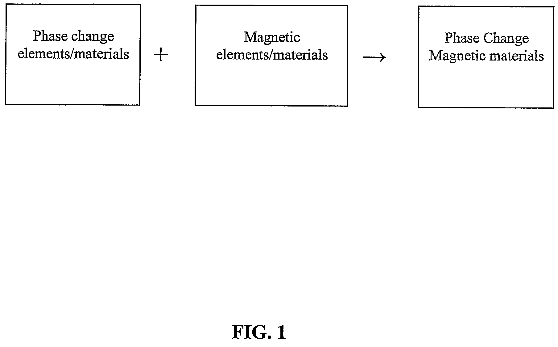
The invention relates to a phase change magnetic composite material for use in an information recording medium, said material comprising a phase change material component, and a ferromagnetic material component, wherein said material exhibits both magnetic effects and phase change effects, and is usable for optical media, phase change random access memory (PCRAM) devices, magnetic random access memory (MRAM) devices, solid state memory devices, sensor devices, logical devices, cognitive devices, artificial neuron network, three level device, control device, SOC (system on chip) device, and semiconductors.

Description

[0001]This invention relates to a novel material, in particular, a novel phase change magnetic material and methods of making the same. The invention also relates to the uses of the material in optical media, phase change random access memory (PCRAM) devices, magnetic random access memory (MRAM) devices, solid state memory devices, sensor devices, logical devices, cognitive devices, artificial neuron network, three level device, control device, SOC (system on chip) device, and semiconductors.BACKGROUND OF THE INVENTION[0002]Over the last three decades, materials for rewritable media have been receiving an increasing amount of interest in the scientific community and the industry. Since the discovery of chalcogenide film materials in 1968, materials have developed into a complex technology which find uses in many important applications, including electrical write and erase non-volatile memory devices, cognitive semiconductors, and rewritable optical discs.[0003]Recent research effort...

Claims


Application Information

Patent Timeline
IPC IPC(8): H01F10/10G11B11/00G11B13/00G11B11/14H01F1/00H01F1/04G11B7/243G11B7/2433
CPCG11B5/02Y10T428/24942G11B7/00454G11B7/243G11B11/10586G11B2005/0002G11B2007/24308G11C11/14G11C13/0004H01F10/193H01F41/18H01F41/205H01F41/22H01F41/26H01F41/30H01L45/06H01L45/1233H01L45/126H01L45/143H01L45/144H01L45/148H01L45/1625Y10T428/32Y10T428/115G11B5/65H10N70/8413H10N70/8825H10N70/884H10N70/231H10N70/026H10N70/8828H10N70/826G11B5/657
Inventor SHI, LUPINGSONG, WENDONGMIAO, XIANGSHUICHONG, TOW CHONG
Owner AGENCY FOR SCI TECH & RES
Learn More