[0006]In accordance with the present invention, a system and method is disclosed that can be used to determine and report on the position of a
wireless device of a user relative to a group of other remote wireless devices dispersed within a
geographic area. For example, the geographic area may correspond to a
residential property, a commercial building, a campus, or an urban neighborhood. To increase the range of the presently disclosed system, some of the devices may be located on
cellular telephone towers or other points of high
visibility, while other devices may be stationary or mobile and situated within the range of the towers. The presently disclosed system and method provides device position information with increased accuracy and reduced cost. In addition, the device whose position is to be determined may be configured to have a
reduced size and reduced power requirements, thereby making the device suitable for use within small autonomous vehicles or robots, suitable for being worn by young children, or suitable for being attached to pets.
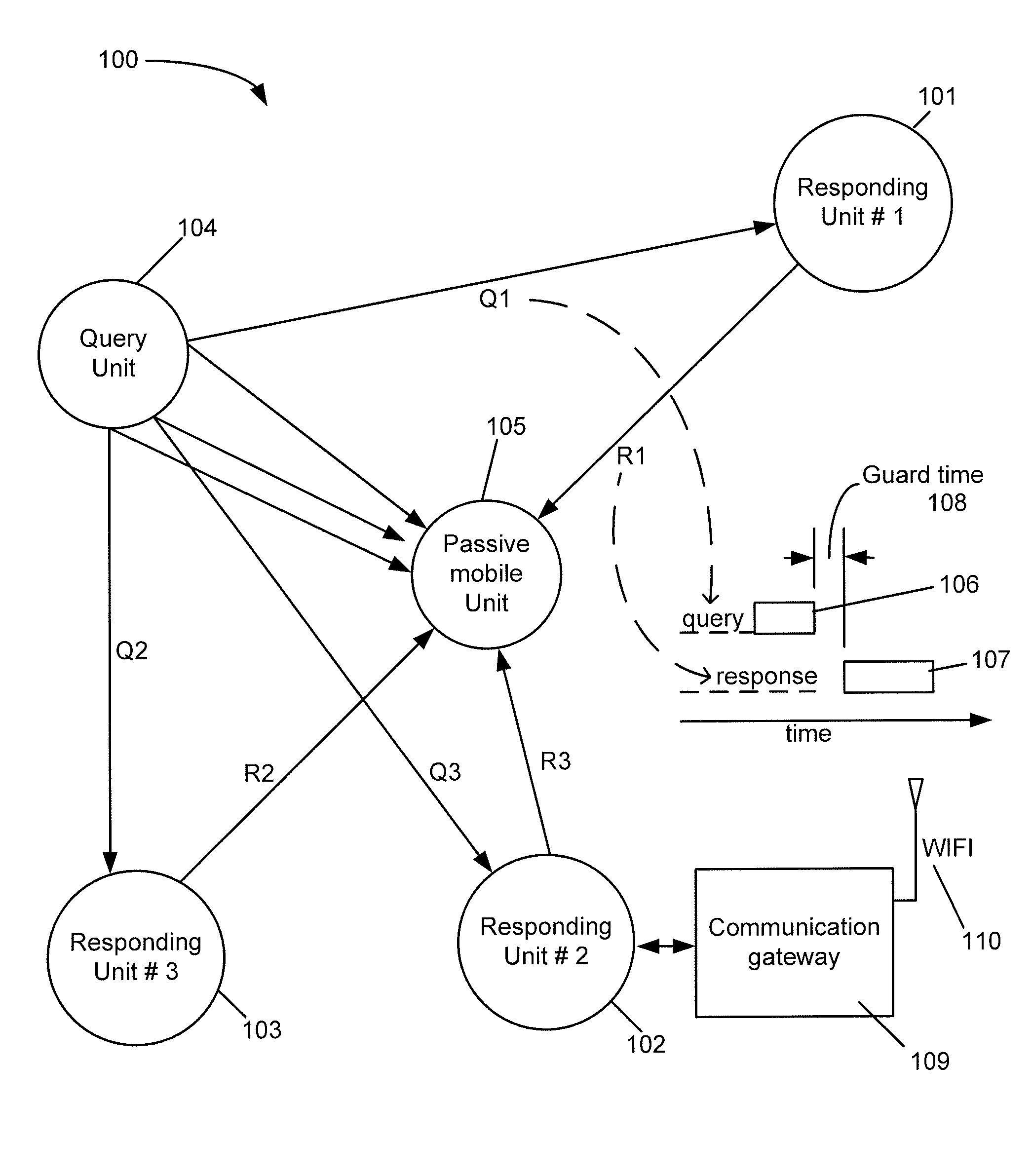
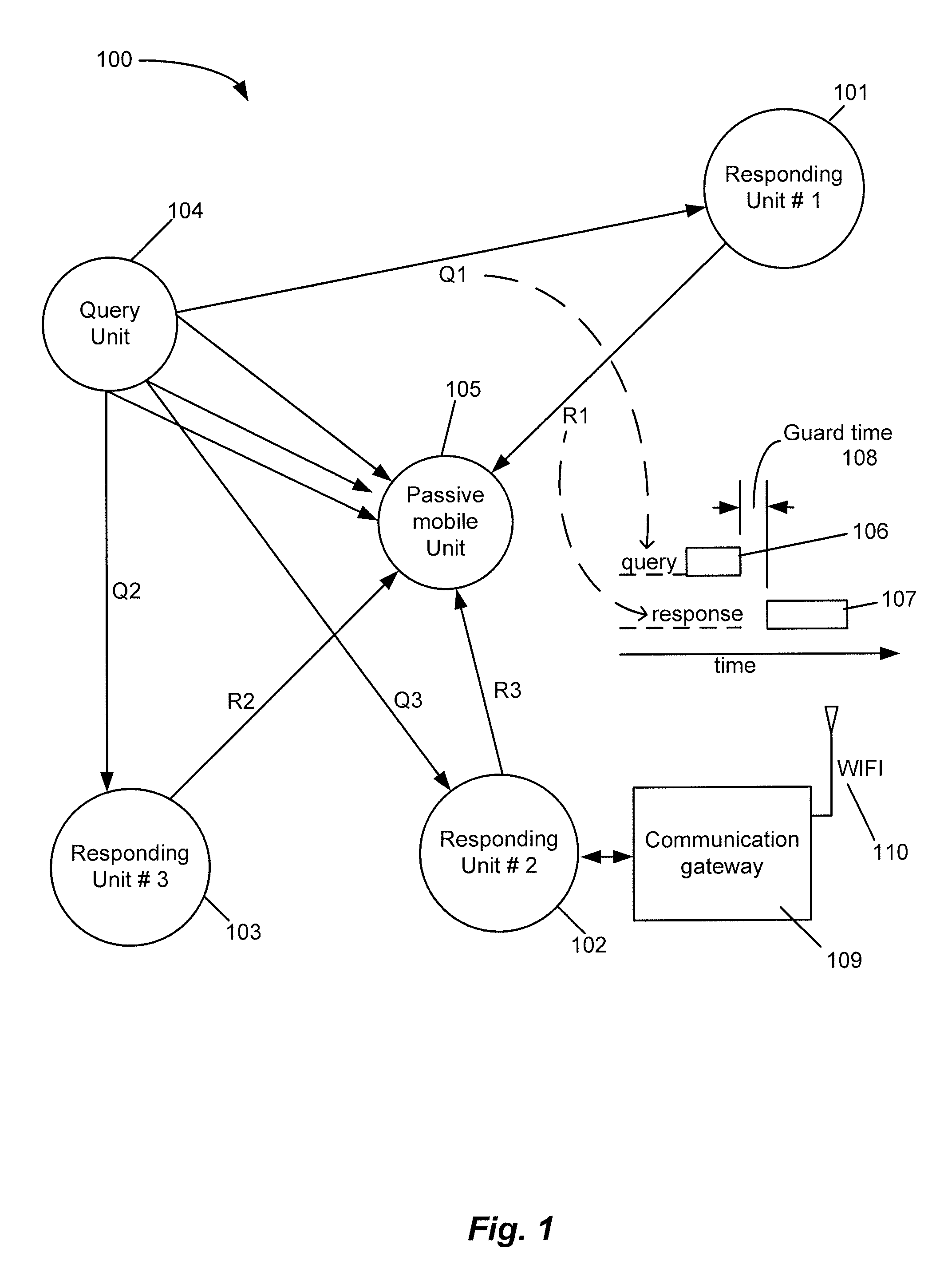
[0009]In a first embodiment of the presently disclosed system, the Query Unit is mobile and operative to query sequentially the plurality of Responding Units, thereby generating a set of pseudo-range measurements based on the
propagation delay times associated with the response messages transmitted by the Responding Units and received at the Query Unit. Each pseudo-range measurement can effectively be obtained by comparing the
time signal generated by the Responding Unit's
clock to the
time signal generated by the Query Unit's clock to determine the
propagation delay time and, based on the
propagation delay time, the range. The Query Unit then uses this set of pseudo-range measurements to determine its own position relative to the Responding Units. For example, the Query Unit may employ a
triangulation technique like that employed in GPS receivers, or any other suitable position computation technique.
[0011]Because the accuracy of propagation
delay time measurements is subject to multi-path effects, in one embodiment, the presently disclosed system is configured to apply a first
Kalman filter to the TOAs of the respective codes contained in a query or response message packet to improve the accuracy of the TDOA measurements associated with each query-response exchange. Next, the system determines the intersection of multiple TDOA hyperbolae to obtain the coordinates of the passive Mobile Unit, and employs a second
Kalman filter to determine a trajectory of the unit that is smoothed and acceleration-gated. The system may also employ a phase weighting
algorithm, taking into account that the direct RF
signal path to the unit will be the shortest path in a group of paths of varying length, and that the phase of an arriving query / response message
signal will tend to be correct at the local maxima and minima of the signal amplitude. In addition, inertial guidance inputs, for example, from low cost MEMS-based accelerometers, may be used to mitigate sudden shifts in apparent position and the resulting large accelerations, which can result from a mobile unit entering or leaving an area where a multipath signal is strong.
[0013]In each of the illustrative embodiments described above, the presently disclosed system can be implemented as a half-
duplex system, thereby allowing the RF sections within the Query and Responding Units to be constructed using low cost commodity components with reduced filter requirements. Further, because a simple form of
phase shift keying (PSK) modulation is employed, the need for high
amplifier and
receiver linearity and
high resolution analog-to-
digital conversion (ADC) circuitry (which characterizes current WIFI,
WIMAX, and
cellular telephone signal structures) is avoided. Moreover,
digital signal processing (DSP) in the respective units can be implemented using standard DSP methods instantiated in
ASIC technology. In addition, clock errors, including those resulting from low cost
crystal timing sources, are minimal due to the short time periods during which
clock drift might influence the propagation
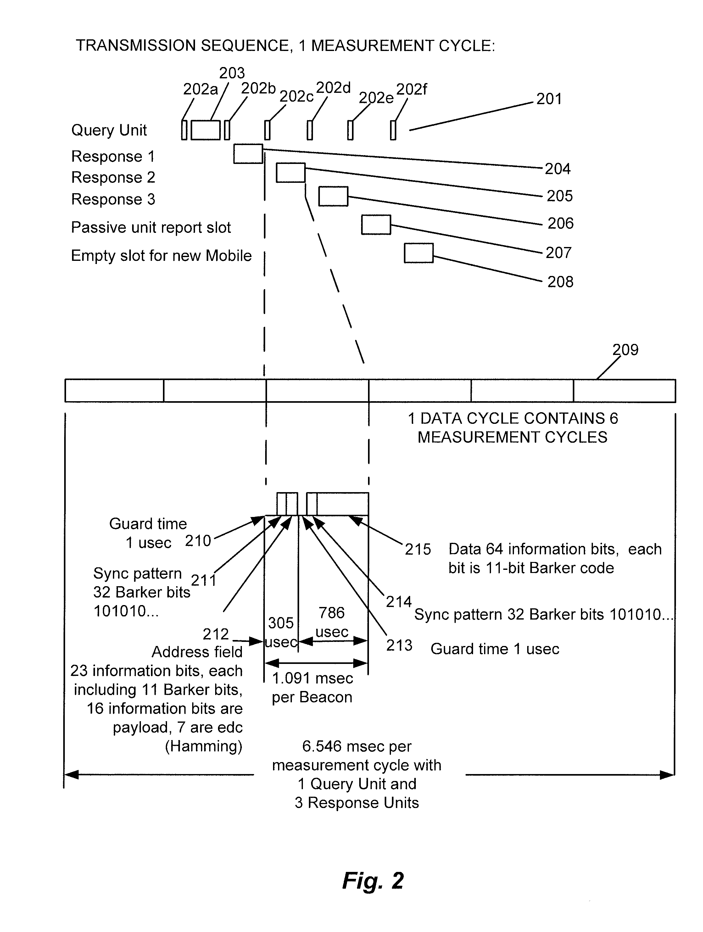
delay time measurements. Further, because the system performs numerous filtered measurements (i.e., one measurement per information bit in the query / response message), the effects of short-term
phase noise are reduced. Because numerous
ranging measurements are performed during each query-response exchange (e.g., one measurement per information bit), improved accuracy can also be achieved by averaging over many readings whose error sources are substantially statistically independent of one another.

