
Systems for detecting unconfined-plasma events

Active Publication Date: 2009-06-18
LAM RES CORP
View PDF18 Cites 57 Cited by
  • Summary
  • Abstract
  • Description
  • Claims
  • Application Information

AI Technical Summary

Benefits of technology

[0015]The invention relates, in an embodiment, to an arrangement within a plasma processing environment of a plasma chamber for detecting an unconfined-plasma event. The arrangement includes a sensor, which is implemented within the plasma chamber and outside of a plasma confinement region. The sensor may produce a transient current during an unconfined-plasma event. The arrangement also includes an insulator to electrically isolate the sensor from the plasma chamber wall. The arrangement further includes a conducting contact to electrically connect a cable, wire, or conductor to the sensor through the insulator. T

Problems solved by technology

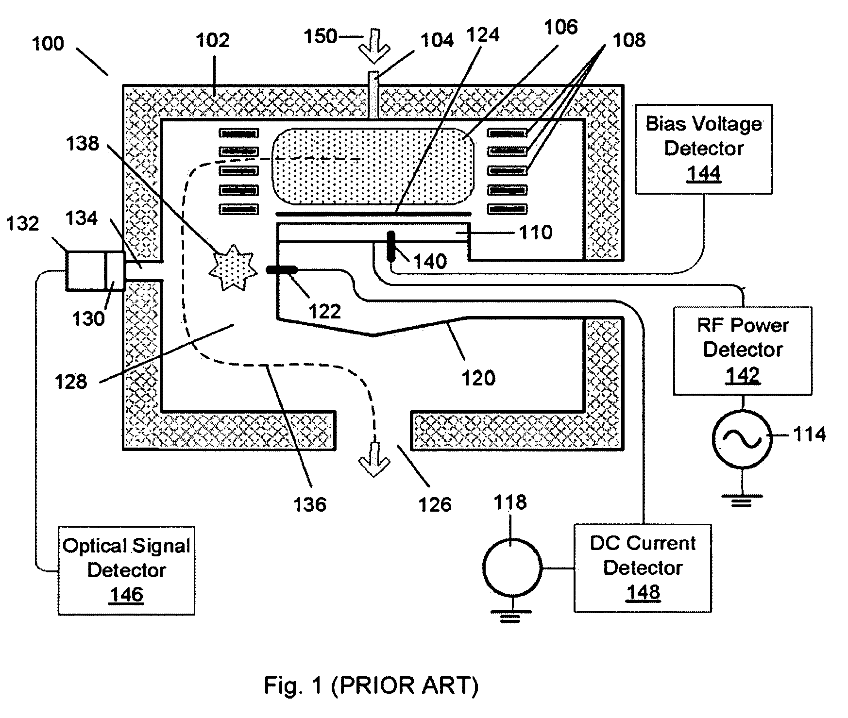
In addition, components of processing chamber 102 may experience electrical damage because unconfined plasma 138 may change the path by which plasma power is returned to ground through the chamber.
For example, a plasma may become unconfined if the plasma becomes unstable.
Also, the occurrence of the unconfined-plasma events may be sporadic and may tend to be unpredictable.
In addition, the specific effects that an unconfined-plasma event may have on substrate processing generally cannot be anticipated due to the variable and unpredictable forms exhibited by unconfined plasma.
However, the operational requirements of Langmuir-style probes (i.e., that the electrodes are unprotected and that a DC electrical contact with the plasma exists) limit the utility of the Langmuir-style probes in detecting unconfined-plasma events.
Also, due to the unpredictable nature of the unconfined-plasma events, the Langmuir-style probes may have to be operating continuously while the substrate is being processed in order to be effective.
However, continuous usage may result in exposing the unprotected electrodes of the Langmuir-style probes to the mixture of chemical species that is usually present in the chamber during plasma processing.
The mixture of chemical species, which includes chemicals supplied for processing of the substrate, new chemical species generated within the processing plasma, and chemical byproducts formed during the processing of the substrate, typically includes both corrosive components and depositing components that may detrimentally affect the ability of Langmuir-style probes to function properly.
In an example, corrosive components (e.g., chlorine, fluorine, and bromine, etc.) may cause the Langmuir-style probe to function improperly, such as failing to timely and / or accurately detect an unconfined-plasma event.
In addition, corroded electrodes may become a source of particulate defects and / or metallic contamination that may indirectly damage the substrate being processed.
In another example, the depositing components of the mixture (e.g., inorganic SiOx-based byproducts and organic CFx-based polymerizers) may result in the formation of an electrically-insulating film on the electrodes of the probe; thus, the film may interfere with the required plasma-electrode DC contact, thereby preventing the probe from accurately and / or timely sensing the presence of a plasma.
As can be appreciated from the foregoing, the Langmuir-style probes may not be ideal for detecting unconfined-plasma events.
However, the utility of monitoring the bias voltage to detect unconfined-plasma events is limited by the difficulty in detecting changes in the bias voltage caused by unconfined-plasma events.
Detecting changes in bias voltage is particularly difficult when higher frequency generators (such as 60 MHz) are utilized to generate plasma.
The bias voltage generated by higher frequency generators is small; and since unconfined-plasma events usually occur at lower power levels, detecting the unconfined-plasma event from the small changes in the DC bias signal may be difficult or impossible.
Therefore the utility of this technique is limited because of the inability to reliably detect unconfined-plasma events.
However, employing the optical sensor to detect unconfined-plasma events may be unsatisfactory in some cases because detecting the light emitted from unconfined plasma 138 may be difficult.
In addition, the positioning of the optical sensor outside of the chamber may make “seeing” the light difficult through the transparent window since the reactive chemicals may cause the transparent window to be less than transparent.
In other words, the reactive chemicals may cause a layer of films to be deposited on the transparent window, thereby significantly reducing the amount and / or quality of light that is detected by the optical sensor.
However, placing windows and / or viewing passages in all locations that may have to be monitored may not always be feasible.

Method used


Image

  • Systems for detecting unconfined-plasma events
  • Systems for detecting unconfined-plasma events
  • Systems for detecting unconfined-plasma events

Examples


Embodiment Construction

[0029]The present invention will now be described in detail with reference to a few preferred embodiments thereof as illustrated in the accompanying drawings. In the following description, numerous specific details are set forth in order to provide a thorough understanding of the present invention. It will be apparent, however, to one skilled in the art, that the present invention may be practiced without some or all of these specific details. In other instances, well known process steps and / or structures have not been described in detail in order to not unnecessarily obscure the present invention.

[0030]Various embodiments are described herein below, including methods and techniques. It should be kept in mind that the invention might also cover articles of manufacture that include a computer readable medium on which computer-readable instructions for carrying out embodiments of the inventive technique are stored. The computer readable medium may include, for example, semiconductor, ...


PUM

PropertyMeasurementUnit
Electric potential / voltageaaaaaaaaaa
Widthaaaaaaaaaa
Frequencyaaaaaaaaaa

Abstract

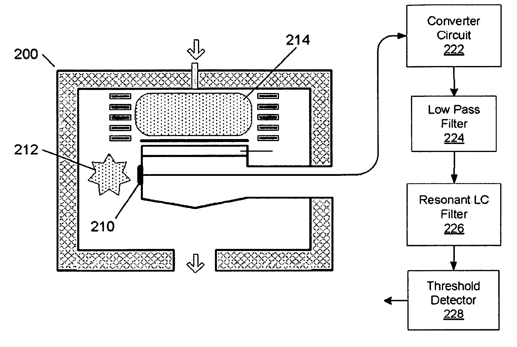
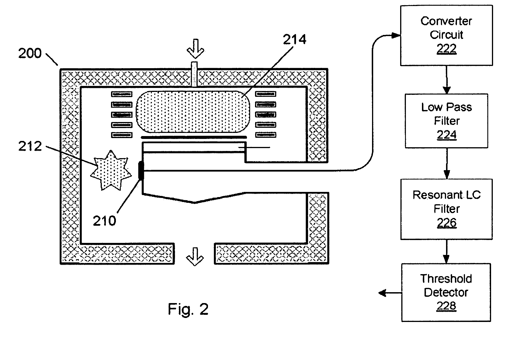
A system for detecting unconfined-plasma events in a plasma processing chamber is disclosed. The system may include a sensor disposed in the plasma processing chamber for providing a current when unconfined plasma is present in the plasma processing chamber. The system may also include a converter for converting the current into a voltage and a filter for removing noise from the voltage to provide a first signal. The system may also include a detector for determining presence of the unconfined plasma using an amplified level of the first signal and / or the first signal. The system may also include a conductor for coupling the sensor and the converter to conduct the current from the sensor to the converter. The system may also include a shield for enclosing at least a portion of the conductor to at least reduce electromagnetic noise received by the conductor.

Description

RELATED APPLICATIONS[0001]The present invention claims priority under 35 USC 119(e) to a commonly owned provisionally filed patent application entitled “SYSTEMS FOR DETECTING UNCONFINED-PLASMA EVENTS,” U.S. Application No. 61 / 026,991, Attorney Docket No. P1765P / LMRX-P149P1, filed Feb. 7, 2008 by inventors John Pease and Seyed Jafar Jafarian-Tehrani, which is incorporated herein by reference; and a commonly owned provisionally filed patent application entitled “PLASMA UNCONFINEMENT SENSOR,” U.S. Application No. 61 / 013,623, Attorney Docket No. P1689P / LMRX-P151P1, filed Dec. 13, 2007 by inventors Jean-Paul Booth, Alexei Marakhtanov, Rajinder Dhindsa, Luc Albarede, and Seyed Jafar Jafarian-Tehrani, which is incorporated herein by reference.BACKGROUND OF THE INVENTION[0002]Plasma processing systems have long been employed to process substrates (such as semiconductor wafers) to produce integrated circuits. Plasma may be generated in various plasma processing systems, such as electron-cycl...

Claims


Application Information

Patent Timeline
IPC IPC(8): C23F1/00
CPCC23F4/00H05H1/0081H01J37/32935
Inventor PEASE, JOHNJAFARIAN-TCHRANI, SEVED JAFAR
Owner LAM RES CORP
Learn More