Biosensor, thin film electrode forming method, quantification apparatus, and quantificaion method

a technology of thin film electrodes and biosensors, applied in the field of biosensors, thin film electrode forming methods, quantification apparatuses, and quantification methods, can solve the problems of described conventional biosensors z, difficult to make the uniform area of working electrodes, and require advanced printing techniques, etc., to achieve enhanced convenience and safety

Inactive Publication Date: 2009-06-18
PHC HLDG CORP
View PDF39 Cites 24 Cited by
  • Summary
  • Abstract
  • Description
  • Claims
  • Application Information

AI Technical Summary

Benefits of technology

[0022]Since a biosensor is constructed as described above, an electrode part can be defined easily and with a high accuracy, and variations in response of each biosensor can be reduced, resulting in a favorable response. Further, the electrode part is formed in a monolayer of electrical conductive layer, whereby troubles can be reduced and an electrode part with a smooth surface can be formed by a simple method. Since the structure of the electrode part is quite simple, it is possible to easily form biosensors having the same performance.
[0108]Since the quantification apparatus is constructed as described above, it is possible to inform a user of the shortage of the specimen amount supplied to the reagent layer of the specimen supply path of the biosensor, resulting in the quantification apparatus with enhanced convenience and safety.

Problems solved by technology

The above-described conventional biosensor Z has problems to be solved.
Accordingly, the area of the working electrode varies with blurs or sags of various pastes at the printing process, and it is difficult to make the uniform area of the working electrode.
In addition, since the electrode structure is composed of three layers, i.e., Ag, carbon, and insulating paste, it is very complicated and requires an advanced printing technique.
Thus, an incorrect display in the measured value occurs due to the shortage of the specimen quantity.
However, this increases man-day, resulting in an increase in costs, or variations in polishing processing accuracy causes variations in the sensor accuracy.
Therefore, it is required a strict control for mass manufacture of stable sensors, resulting in considerable troubles.
Further, only by applying the reagent on electrodes for the reagent layer formation, the reagent cannot uniformly be applied on the electrodes because of the surface state of the electrode or a difference in the way in which the reagent spreads due to reagent liquid composition, whereby variations in the reagent quantity on the electrodes occur.
Therefore, the performance of the biosensor Z is deteriorated.
Further, it is considerably troublesome to insert the correction chip for every measurement, and when it is forgotten to insert the correction chip, a correction chip for example for measuring lactic acid value is inserted by mistake, or a correction chip which is for measuring blood sugar level but has different output characteristics is inserted, there occurs an error in a measured result.

Method used


Image

  • Biosensor, thin film electrode forming method, quantification apparatus, and quantificaion method
  • Biosensor, thin film electrode forming method, quantification apparatus, and quantificaion method
  • Biosensor, thin film electrode forming method, quantification apparatus, and quantificaion method

Examples


embodiment 1

[0135]A biosensor A as defined in claims 1 to 10 of the present invention will be described as a first embodiment with reference to the figures.

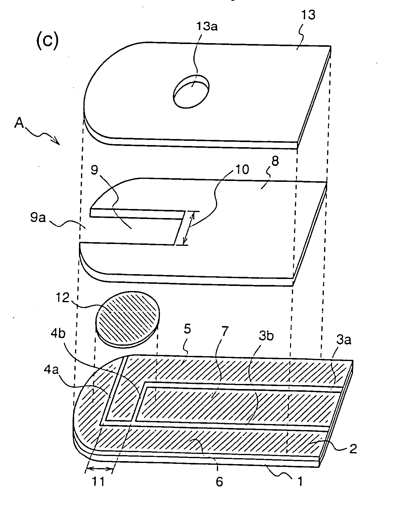
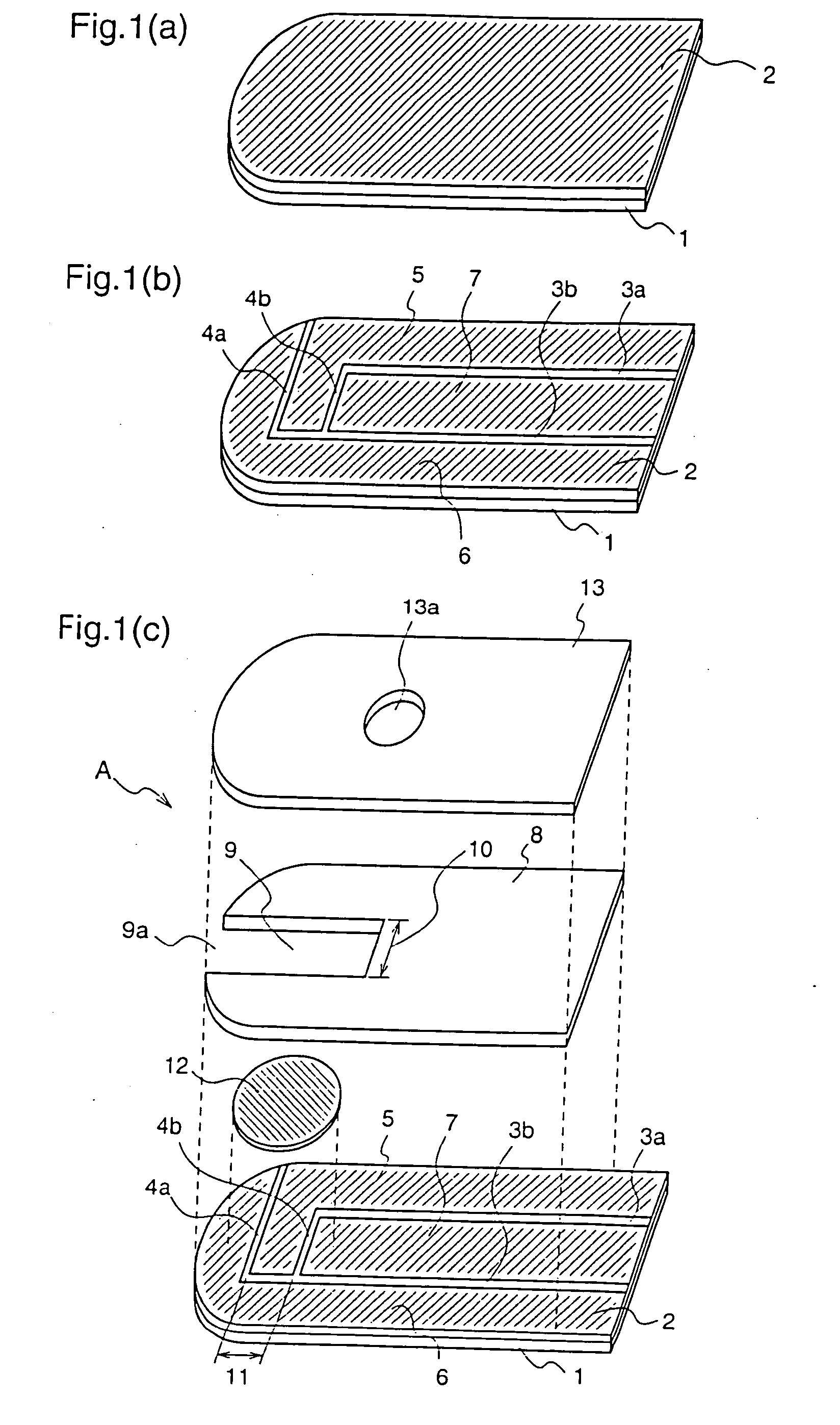
[0136]FIGS. 1(a) to 1(c) are exploded perspective views of the biosensor A according to the first embodiment of the present invention.

[0137]First, members constituting the biosensor A will be described.

[0138]Numeral 1 denotes a first insulating support (hereinafter, referred to as merely “support”) composed of polyethylene terephthalate or the like. Numeral 2 denotes a conductive layer which is formed on the whole surface of the support 1 and composed of an electrical conductive material such as a noble metal, for example gold or palladium, and carbon. Numerals 3a and 3b denote slits which are provided on the conductive layer 2 on the support 1 and are parallel to the side of the support 1. Numerals 4a and 4b denote slits which are provided on the conductive layer 2 on the support 1 and are vertical to the side of the support 1. Numerals 5, ...

embodiment 2

[0150]A biosensor B according to claims 11 and 12 of the present invention will be described as a second embodiment.

[0151]FIG. 3 are perspective views illustrating the biosensor B in the order of the manufacturing process, and FIG. 4 is a diagram illustrating a specimen supply path of the biosensor B.

[0152]First, the structure of the biosensor B will be described.

[0153]Numeral 21 denotes an insulating support which is composed of polyethylene terephthalate or the like. Numeral 22 denotes an electrical conductive layer which is formed on the whole surface of the support 21 and is composed of an electrical conductive material such as noble metal, for example gold or palladium, and carbon. Numerals 23a, 23b, 23c and 23d denote first slits which are provided on the electrical conductive layer 22. Numerals 25, 26 and 27 denote electrodes which are formed by dividing the electrical conductive layer 22 by the first slits 23a, 23b, 23c and 23d, i.e., a working electrode, a counter electrode...

embodiment 3

[0165]A specific method for manufacturing the above-described biosensors A and B will be further described. Here, the biosensors A and B are assumed a biosensor X collectively.

[0166]FIG. 23 is a top view illustrating a state where the slits are formed on an electrical conductive layer provided on a surface of a sensor wafer P as a basis of the biosensor X.

[0167]Numeral 3102 denotes an electrical conductive layer composed of carbon, a metal material or the like, which is provided on the whole surface of a support 3101. Numerals 3103a, 3103b, 3103c and 3103d denote slits which are formed on the electrical conductive layer 3102. Numerals 3105, 3106 and 3107 denote electrodes which are formed by dividing the electrical conductive layer 3102 by the slits 3103a, 3103b, 3103c and 3103d, i.e., a working electrode, a counter electrode and a detecting electrode. Numeral 3110 denotes a cutting plane line showing a cutting position of the support. The sensor wafer P is a support in a state wher...


PUM

PropertyMeasurementUnit
widthaaaaaaaaaa
slit widthaaaaaaaaaa
thicknessaaaaaaaaaa

Abstract

A biosensor according to the present invention comprises a support 1, a conductive layer 2 composed of an electrical conductive material such as noble metal, for example gold, palladium or the like, and carbon, slits 3a and 3b parallel to the side of the support 1, slits 4a and 4b vertical to the side of the support 1, a working electrode 5, a counter electrode 6, a detecting electrode 7, a spacer 8 which covers the working electrode 5, the counter electrode 6 and the detecting electrode 7 on the support 1, a rectangular cutout part 9 forming a specimen supply path, an inlet 9a of the specimen supply path, a reagent layer 12 formed by applying a reagent including an enzyme or the like to the working electrode 5, the counter electrode 6 and the detecting electrode 7, which is exposed from the cutout part 9 of the spacer 8, and a cover 13 which covers the spacer 8, as shown in FIG. 1. The so-constructed biosensor can be formed by a simple method, and a biosensor which is excellent in a measuring accuracy as well as a biosensor in which a reagent layer is placed uniformly on the electrodes regardless of a reagent liquid composition, and which has a uniform performance can be realized.

Description

TECHNICAL FIELD[0001]The present invention relates to a biosensor which quantifies a substrate included in a sample liquid, a thin film electrode forming method suitable at the manufacture of this biosensor, as well as a quantification apparatus and a quantification method using the biosensor and, more particularly, to a biosensor which provides a low manufacture error and a stable performance, a thin film electrode forming method used in manufacturing electrodes of the biosensor, as well as a quantification apparatus and a quantification method using the biosensor.BACKGROUND ART[0002]A biosensor is a sensor which utilizes a molecule recognizing capacity of a biological material such as microorganisms, enzymes, antibodies, DNA, and RNA and applies a biological material as a molecular discrimination element to quantify a substrate included in a sample liquid. That is, the substrate included in the sample liquid is quantified by utilizing a reaction which is caused when a biological m...

Claims


Application Information

Patent Timeline
Patent Type & Authority Applications(United States)
IPC IPC(8): C12M1/00C12Q1/00
CPCC12Q1/001Y10T29/49002G01N33/48771G01N27/3272G01N27/26
Inventor MIYAZAKI, SHOJITOKUNAGA, HIROYUKIFUJIWARA, MASAKIYAMANISHI, ERIKOTOKUNO, YOSHINOBU
Owner PHC HLDG CORP
Why Eureka
Try Eureka