Load controller

a technology of load controller and input part, which is applied in the direction of ignition automatic control, pulse technique, instruments, etc., can solve the problems of large amount of dark current supplied, deterioration of the accuracy of the operating threshold value voltage of the input part, and a large amount of malfunction, so as to improve the accuracy of the input voltage determination, the effect of reducing the cost and improving the accuracy of the input voltag

Active Publication Date: 2009-06-18
YAZAKI CORP +1
View PDF9 Cites 14 Cited by
  • Summary
  • Abstract
  • Description
  • Claims
  • Application Information

AI Technical Summary

Benefits of technology

[0013]Thus, by considering the above-described problems, it is an object of the present invention to provide a load controller that can reduce a dark current when a load is driven and PWM-controlled by a drive instruction.
[0016]According to the above configuration, in a load controller that operates in response to the drive instruction signal of a low level (Lo) to drive a load, the first input threshold value is set by the input circuit having no hysteresis to detect the drive instruction signal. The constant current source is activated in accordance with the detected result. The comparator and the PWM signal generating unit are further activated by the activated constant current source. The PWM drive control signal is generated in accordance with the compared result of the second input threshold value set to be lower than the first input threshold value with the drive instruction signal by the comparator and the PWM signal supplied from the PWM signal generating unit. The load driving element is driven by the generated PWM drive control signal to PWM-control the load. Accordingly, when a drive instruction is not carried out, a dark current can be suppressed substantially zero, a determining accuracy of an input voltage can be improved at the same time. Further, since these structures are simpler than those of a usual device, the device can be made to be more compact and a cost can be lowered.
[0017]According to the above configuration, when the comparator having the hysteresis is used as the comparator, a highly accurate input determination that is strong to noise can be realized.

Problems solved by technology

Further, in the load controller, when the dark current is zero during turning off an input, the accuracy of an operating threshold value voltage of an input part is deteriorated so that a malfunction is liable to occur due to noise or the like.
Thus, a problem arises that a large amount of dark current is supplied.
Further, in the load controller disclosed in JP-A-2004-248093, when the current cut-off switching elements are added to all the control parts in a circuit, a dark current can be suppressed substantially to zero, however, a problem arises that the scale of the circuit is enlarged to enlarge the device.
Further, when the input processing circuit disclosed in JP-A-2007-159059 tries to be applied to the load controller, a problem arises that the dark current is suppressed only in the input part, but is supplied to other parts.
Further, another problem arises that elements forming the circuit such as an inverter for enabling the Schmitt circuit or the comparator are increased to enlarge the scale of the circuit.

Method used


Image

  • Load controller
  • Load controller
  • Load controller

Examples


Embodiment Construction

[0023]Now, an embodiment of the present invention will be described below by referring to the drawings.

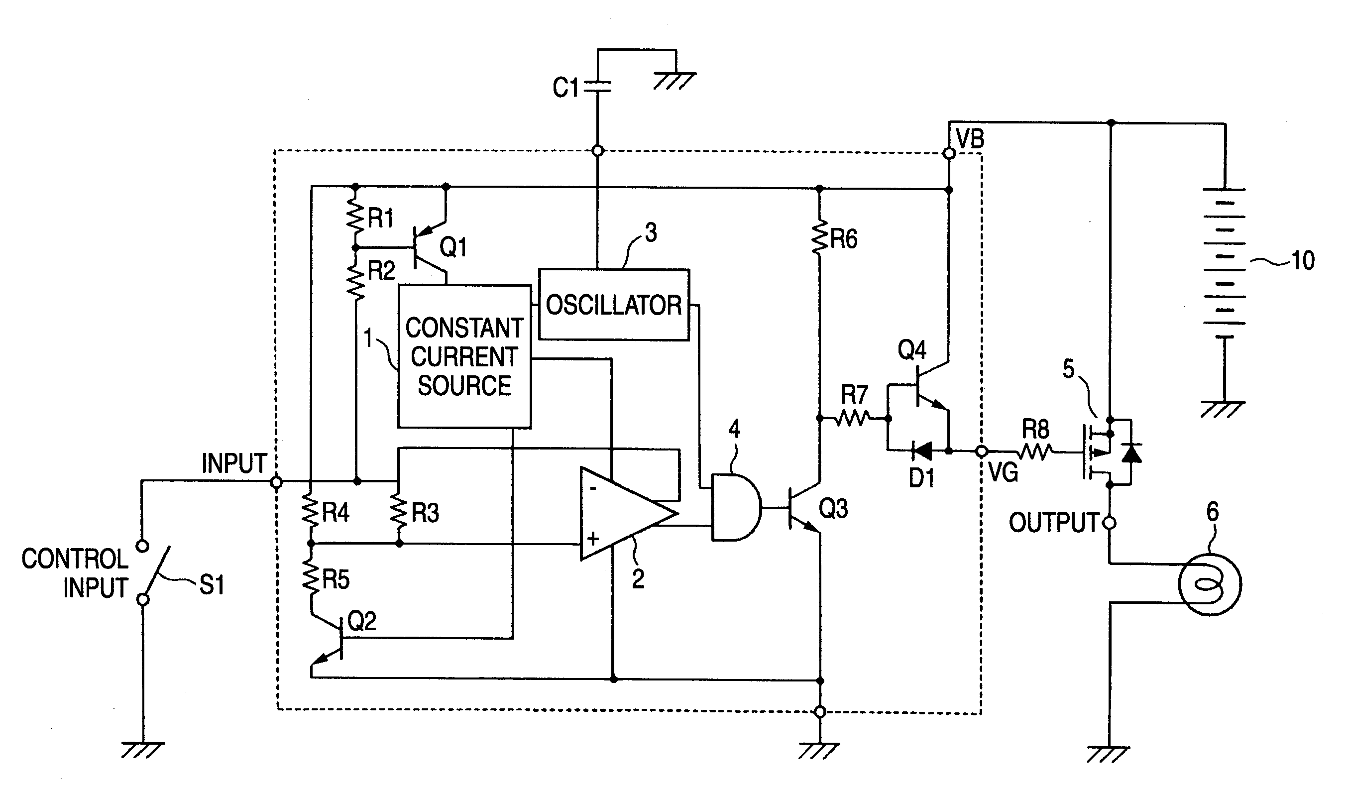
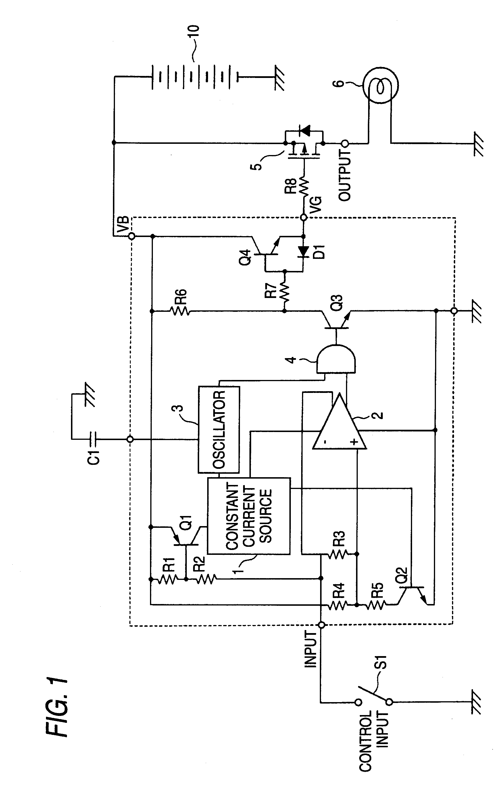
[0024]FIG. 1 is a circuit diagram showing an embodiment of a load controller according to the present invention. In this embodiment, a case will be described that a lamp (for instance, a head lamp, etc.) mounted on a vehicle as a load is PWM-controlled.

[0025]In FIG. 1, the load controller includes transistors Q1 to Q4, resistances R1 to R8, a capacitor C1, a diode D1, an input switch S1, a constant current source 1, a comparator 2, an oscillator 3, an AND gate 4, a P channel MOSFET (refer it to as a PMOSFET, hereinafter) 5, a lamp 6 mounted on a vehicle as a load and a battery 10.

[0026]As a switch element having no hysteresis, a pnp-typed transistor Q1 is provided and the constant current source 1 is driven by the pnp-typed transistor Q1. The resistance R1, the resistance R2 and the transistor Q1 form an input circuit in which a first input threshold value Vth is set. The emitter o...


PUM


Abstract

A load controller includes: an input circuit which detects that a drive instruction signal is less or equal to a first input threshold value; a constant current source activated in accordance with a detection by the input circuit; a PWM signal generating unit that is activated by the constant current source and generates a PWM signal; a comparator that is activated by the constant current source and compares the drive instruction signal with a second input threshold value set to be lower than the first input threshold value; a logic calculation unit that carries out a logic calculation of the PWM signal with a compared result of the comparator; a drive control unit that operates in accordance with an output from the logic calculation unit to generate a PWM drive control signal; and a load driving element that is driven by the PWM drive control signal to control a load.

Description

BACKGROUND OF THE INVENTION[0001]1. Technical Field[0002]The present invention relates to a load controller, and more particularly to a load controller that PWM-controls a load.[0003]2. Background Art[0004]In vehicles, some of devices are required to operate in accordance with a drive instruction by the input of a control signal from an input switch even in a state that an ignition switch is turned off. In such devices, when the input switch is turned off, a current (dark current) needs to be lowered as much as possible, preferably to be set to zero from the viewpoint of a protection of a battery.[0005]Thus, when a device is to be realized in which a PWM (Pulse Width Modulation) output operation is carried out by inputting a control signal (fixed input) under a state that an ignition switch is turned off, for instance, a load controller is found that is disclosed in JP-A-2001-148294. In this load controller, a load is PWM-controlled by a drive control signal whose frequency and duty...

Claims


Application Information

Patent Timeline
Patent Type & Authority Applications(United States)
IPC IPC(8): G05F1/00
CPCH03K5/088H03K2217/0036H03K7/08
Inventor YABE, HIROOUCHIKURA, TSUYOSHITASHIRO, TATSUMITANAKA, AKIHIROKASAI, MASAHIRO
Owner YAZAKI CORP
Why Eureka
Try Eureka