Lithium ion capacitor

a technology of lithium ion and capacitor, which is applied in the field of lithium ion capacitor, can solve the problems of long time for lithium ions, substantial difficulty in increasing the number of lithium metals to be disposed, and disadvantages of industrialization, so as to reduce potential, increase capacitance, and increase the number of electrodes in the cell.

Active Publication Date: 2009-06-18
SUBARU CORP
View PDF4 Cites 21 Cited by
  • Summary
  • Abstract
  • Description
  • Claims
  • Application Information

AI Technical Summary

Benefits of technology

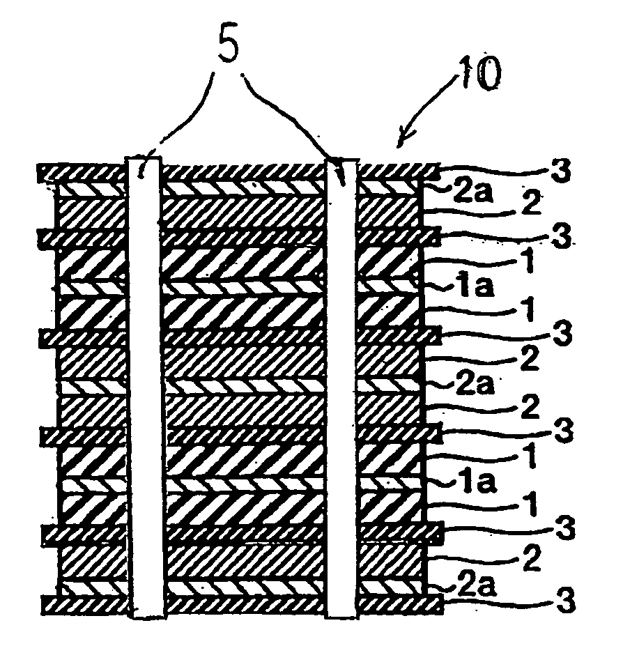
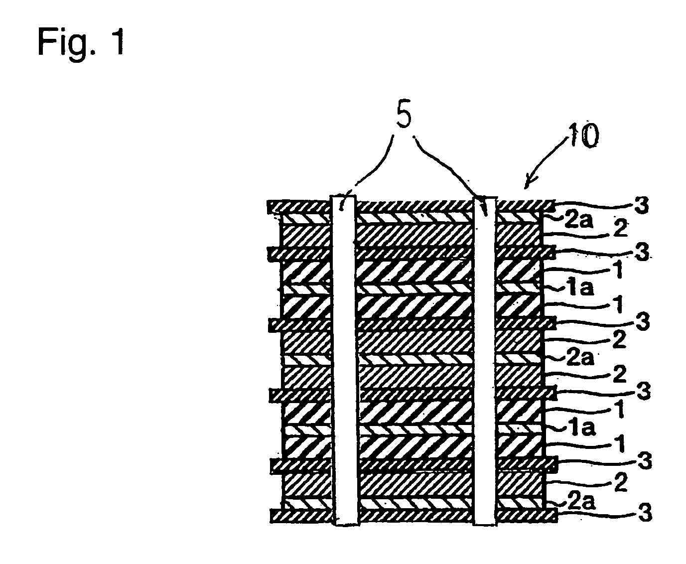
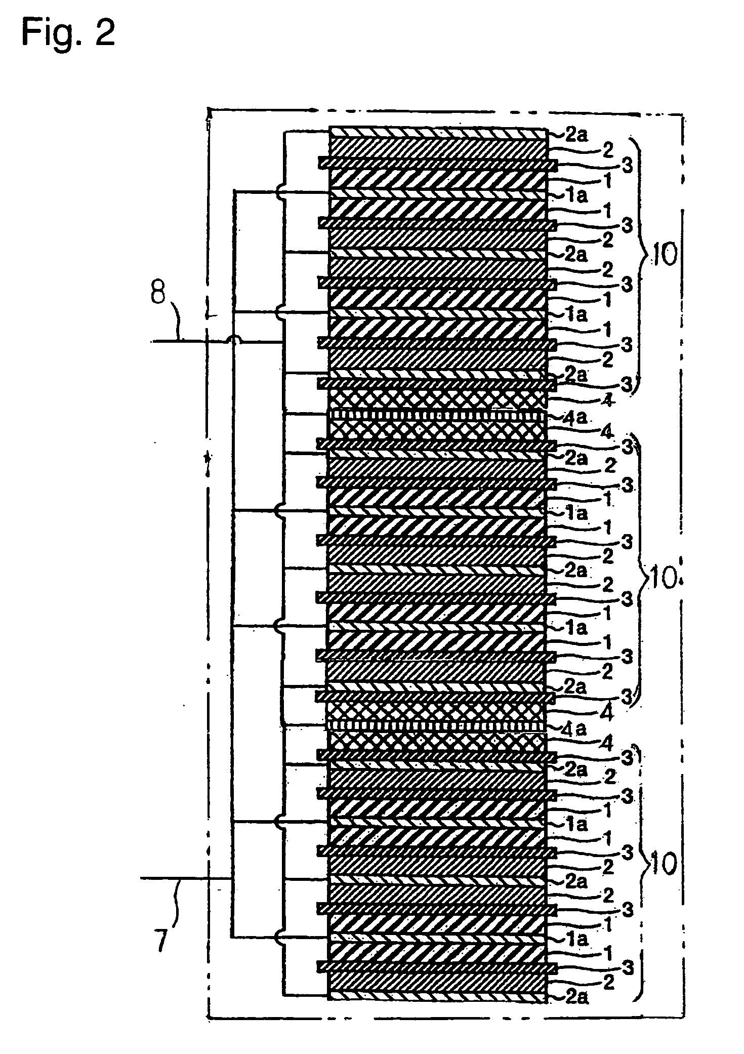
[0016]In the lithium ion capacitor of the present invention, the positive electrode potential and the negative electrode potential are at most 2.0 V after the positive electrode and the negative electrode are short-circuited, each of the positive electrode current collector and the negative electrode current collector has pores penetrating from the front surface to the back surface, a lithium ion supply source is disposed between electrode units each having a positive electrode and a negative electrode alternately laminated with a separator interposed therebetween, and lithium ions are preliminarily supported by the negative electrode and / or the positive electrode by electrochemical contact of the lithium ion supply source with the negative electrode and / or the positive electrode. Accordingly, by charging of this cell, the negative electrode will have a lowered potential and an increased capacitance, and the number of electrodes constituting the cell will easily be increased. Thus, a large-size storage device having a high energy density, a high output density and a large capacity will be obtained. Accordingly, it becomes possible to realize a storage device which can be used for applications for which a large capacity and high output characteristics are required, such as power sources for electric automobiles and for electrical equipment of automobiles.
[0017]Further, by disposing a lithium ion supply source for supporting the negative electrode and / or the positive electrode between the electrode units, the degree of freedom of the cell design and mass productivity will improve and excellent charge and discharge characteristics will be obtained.
[0018]Further, as a cell structure of disposing a lithium ion supply source between electrode units is employed, the number of electrodes laminated to be doped by one layer of the lithium ion supply source can be reduced, and the negative electrode and / or the positive electrode can be doped with lithium ions evenly in a short time, whereby a high quality lithium ion capacitor can be efficiently produced.
[0019]Further, the cell can be formed by assembling at least two electrode units each having a positive electrode and a negative electrode alternately laminated with a separator interposed therebetween, and thus workability in cell assembling can be improved.

Problems solved by technology

However, if the number of electrodes laminated is larger than the above, doping with lithium ions will take long (at least 30 days for example) even under optimum conditions, which is industrially disadvantageous.
Namely, in a conventional lithium ion capacitor, because a cell has a structure in which the negative electrodes are doped with lithium ions from lithium metal disposed on the upper portion, on the lower portion or on the upper and lower portions of the electrode laminate, it is substantially difficult to increase the number of lithium metal to be disposed.
As a result, it has been difficult to realize a storage device which can be used for applications for which a high energy density, a large capacity and high power characteristics are required, such as power sources for electric cars and electrical equipment of automobiles.

Method used


Image

  • Lithium ion capacitor
  • Lithium ion capacitor
  • Lithium ion capacitor

Examples


example 1

Process for Producing Negative Electrode 1

[0095]A phenol resin molded plate having a thickness of 0.5 mm was put in a Siliconit electric furnace and subjected to a heat treatment by increasing the temperature at a rate of 50° C. / hour to 500° C. and further at a rate of 10° C. / hour to 660° C. in a nitrogen atmosphere thereby to synthesize PAS. The PAS plate thus obtained was pulverized with a disk mill to obtain a PAS powder. The PAS powder had a H / C ratio of 0.21.

[0096]Then, 100 parts by weight of the above PAS powder and a solution having 10 parts by weight of a vinylidene polyfluoride powder dissolved in 80 parts by weight of N-methylpyrrolidone were sufficiently mixed to obtain a slurry. This slurry was applied on one surface of a copper foil having a thickness of 18 μm in an amount of about 7 mg / cm2 as a solid content, dried and pressed to obtain a PAS negative electrode 1.

Process for Producing Positive Electrode 1

[0097]100 Parts by weight of a commercial activated carbon powder...

example 2

[0123]Two electrode units were obtained by laminating electrodes so that the positive electrodes and the negative electrodes faced at 20 faces in the same manner as in Example 1. For each electrode unit, 10 positive electrodes and 11 negative electrodes were used. The positive electrode active material weight is 1.4 times the negative electrode active material weight.

[0124]As a lithium electrode, two electrodes having a lithium metal foil (82 μm, 6.0×7.5 cm2, corresponding to 100 mAh / g) pressure bonded on one side of a stainless steel net having a thickness of 80 μm and one electrode having a lithium metal foil (164 μm, 6.0×7.5 cm2, corresponding to 200 mAh / g) pressure bonded on one side were obtained.

[0125]The lithium electrode having lithium metal of 164 μm pressure bonded was disposed between the two electrode units so as to face the electrode units, and the lithium electrodes having lithium metal of 82 μm pressure bonded on one side were disposed on the upper and lower portions ...

example 3

[0130]Five cells of film type capacitors were assembled (lithium metal in each cell corresponded to 400 mAh / g) in the same manner as in Example 2 except that a copper foil of 20 μm was used for the current collector of the lithium electrode.

[0131]20 Days after the cells were left to stand after assembled, one cell was decomposed, whereupon part of lithium metal in the lithium electrode disposed between the electrode units remained, but lithium metal in the lithium electrode disposed on each of the upper and lower portions disappeared. The cells were left to stand further for 20 days and then one cell was decomposed, whereupon lithium metal completely disappeared. Accordingly, it was judged that the negative electrodes were preliminarily charged with lithium ions so as to obtain a capacitance of 650 F / g per unit weight of the negative electrode active material. The capacitance of the negative electrode is 7.2 times the capacitance of the positive electrode.

[0132]In the same manner as...


PUM

PropertyMeasurementUnit
negative electrode potentialaaaaaaaaaa
positive electrode potentialaaaaaaaaaa

Abstract

A lithium ion capacitor including a positive electrode, a negative electrode, and an aprotic organic solvent solution of a lithium salt as an electrolytic solution. The positive electrode active material is capable of reversibly supporting lithium ions and/or anions, the negative electrode active material is capable of reversibly supporting lithium ions and anions, and the potentials of the positive electrode and the negative electrode are at most 2.0 V after the positive electrode and the negative electrode are short-circuited. The positive electrode and the negative electrode are alternately laminated with a separator interposed therebetween to constitute an electrode unit, the cell is constituted by at least two such electrode units, lithium metal is disposed between the electrode units, and lithium ions are preliminarily supported by the negative electrode and/or the positive electrode by electrochemical contact of the lithium metal with the negative electrode and/or the positive electrode.

Description

TECHNICAL FIELD[0001]The present invention relates to a lithium ion capacitor having a high energy density, a high power density and a large capacity.BACKGROUND ART[0002]In recent years, a battery using as a negative electrode a carbon material such as graphite and using as a positive electrode a lithium-containing metal oxide such as LiCoO2, has been proposed. This battery is a so-called rocking chair battery such that after it is assembled, lithium ions are supplied from the lithium-containing metal oxide as the positive electrode to the negative electrode by charge, and lithium ions are returned from the negative electrode to the positive electrode by discharge. This battery is called a lithium ion secondary battery since no lithium metal is used for the negative electrode but only lithium ions are involved in the charge and discharge, and this battery is distinguished from a lithium battery using lithium metal. This battery is characterized by having a high voltage, a large capa...

Claims


Application Information

Patent Timeline
Patent Type & Authority Applications(United States)
IPC IPC(8): H01G9/022H01G9/04H01G11/10H01G11/06H01G11/22H01G11/30H01G11/32H01G11/50H01G11/66H01G11/68H01G11/84H01M4/133H01M4/587
CPCH01G11/06H01G11/12H01G11/28H01G11/38Y02T10/7022H01G11/70H01G11/72H01G11/86Y02E60/13H01G11/62Y02T10/70
Inventor TASAKI, SHINICHIANDO, NOBUONAGAI, MITSURUSHIRAKAMI, ATSUROMATSUI, KOHEIHATO, YUKINORI
Owner SUBARU CORP
Why Eureka
Try Eureka