

Method of curing coatings on automotive bodies using high energy electron beam or x-ray
a technology of electron beam or x-ray and coating, which is applied in the direction of liquid surface applicators, coatings, pretreated surfaces, etc., can solve the problems of radiation curable coatings, radiation curable coatings, as a class, and radiation curable coatings, so as to achieve rapid curing, and eliminate or reduce non-reactive solvent use
- Summary
- Abstract
- Description
- Claims
- Application Information
AI Technical Summary
Benefits of technology
Problems solved by technology
Method used
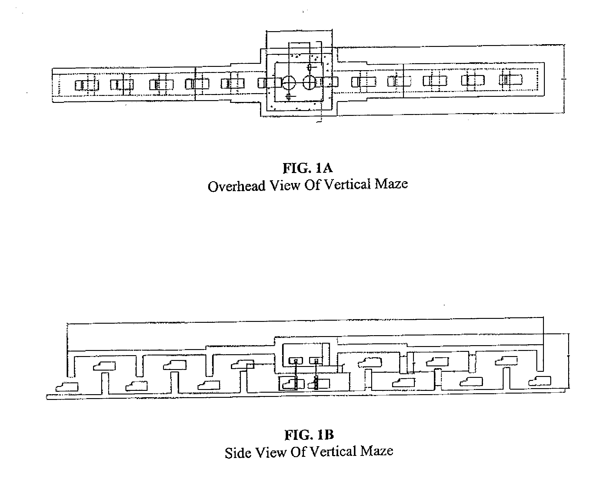
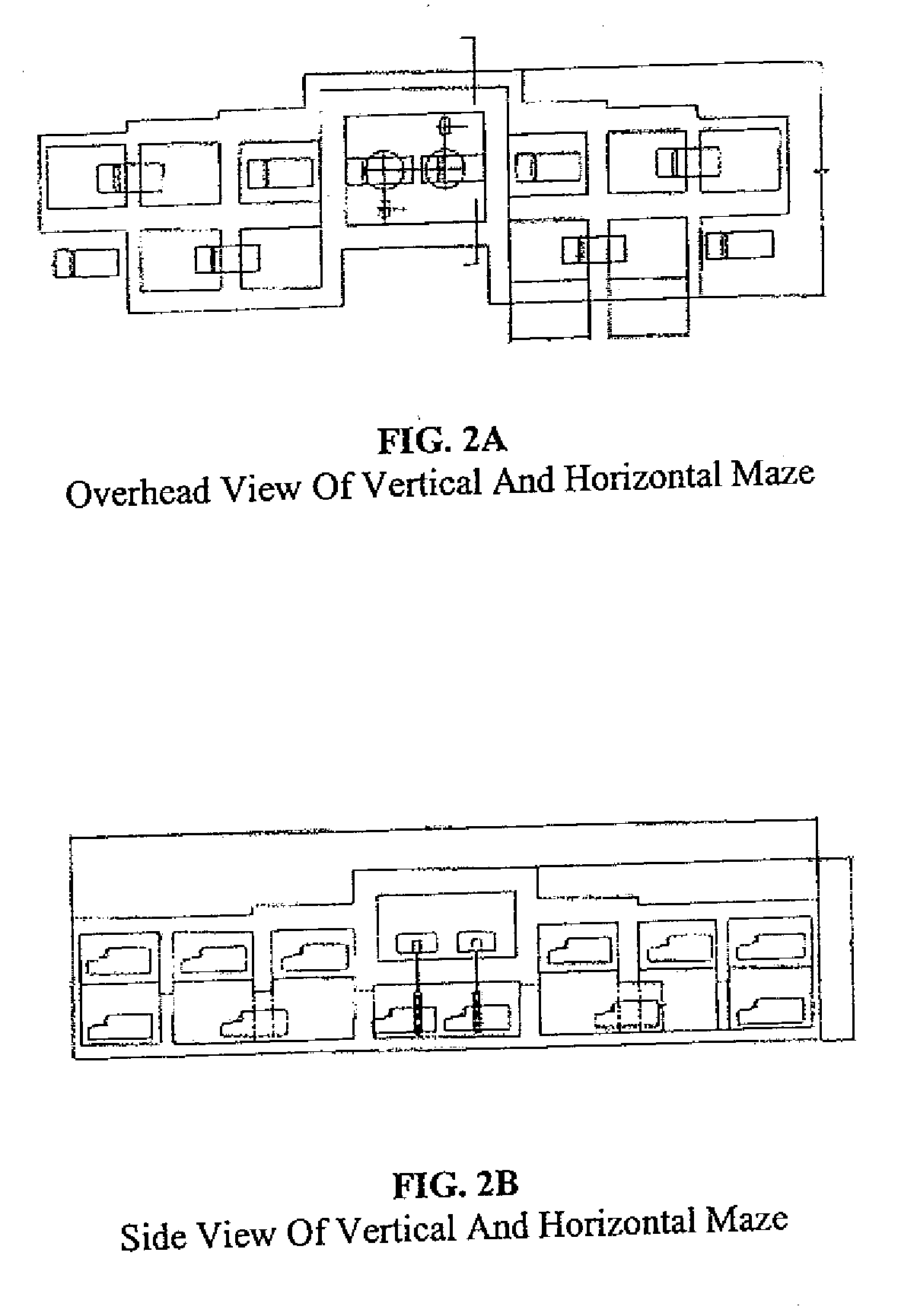
Image

Examples
example 1
7.1 Example 1
Monte Carlo Simulations (Electron Beam)
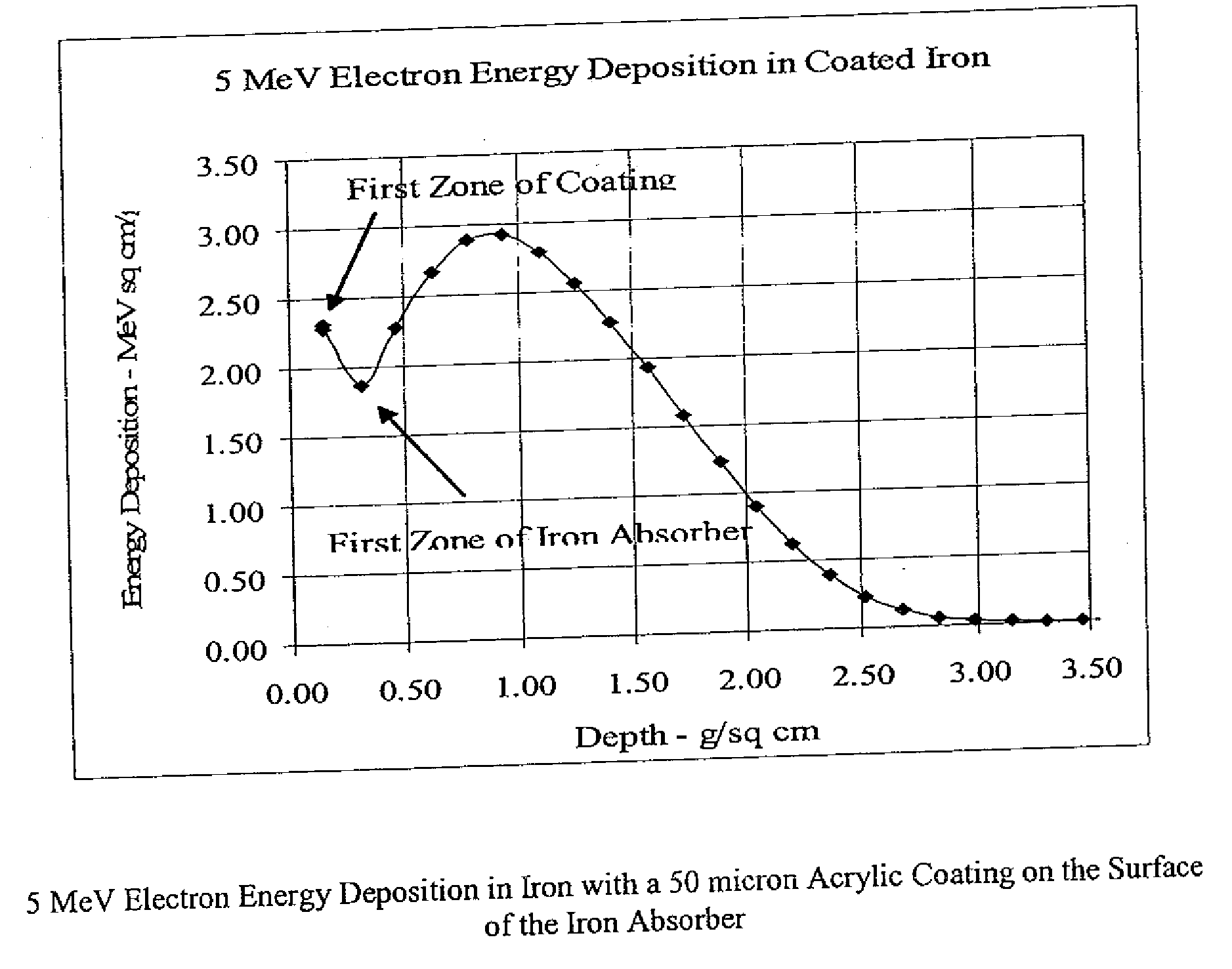
[0096]Calculations were done to estimate the time required to cure coatings on automobile bodies with high-energy electrons. Specifically, the ITS3 TIGER Monte Carlo code was used to calculate the depth-dose distribution in an iron absorber irradiated with 5, 7 and 10 MeV electron beams. In each case, the assumed thickness of the iron was greater than the maximum range of the primary electrons. The surface of the iron was assumed to be covered with an acrylic material to evaluate the difference between the energy deposition (proportional to the absorbed dose) in the coating versus that in the iron.
[0097]The TIGER code only gives one-dimensional dose distributions in flat plates of material with unbounded areas. The output data can be used to calculate the area throughput rates for irradiating large flat surfaces, and to show the variation in absorbed dose within the absorbing materials. However, dose variations at the edges of fini...
example 2
7.2 Example 2
Monte Carlo Simulations (X-Ray)
[0112]Similar calculations were done to estimate the time required to cure coatings on automobile bodies with high-energy X-rays. The results were obtained by using the ITS3 TIGER Monte Carlo code to calculate depth-dose distributions in a thick iron absorber with X-rays generated with 5, 6 and 7 MeV electrons on a typical target assembly. The assumed target structure was thick enough to stop all of the primary electrons from the accelerator. The X-ray “background” of the electron depth-dose distribution extended from the target through the iron absorber beyond the target. This residual “tail” of the depth-dose distribution provided the data needed for this report.
[0113]Initially, three Monte Carlo calculations were made with 5, 6 and 7 MeV electrons on a typical X-ray target. The assumed target materials included a 1.2 mm tantalum converter plate, a 2 mm channel of cooling water and a 2 mm stainless steel backing plate. Once again, iron w...
example 3
7.3 Example 3
Electron Beam Processing of Coated Plates and Plate Stacks
[0129]Fifteen steel plates (4″ by 12″), pretreated with conventional electrocoat and primer, were spray painted with an electron beam curable color (silver) basecoat. After the basecoat all fifteen of the painted plates were spray coated with a conventional clearcoat. Five of these plates were processed individually in a high energy electron beam irradiator (8 kW, 12 MeV) using standard tote trays at increments of 10 kGy up to 50 kGy. The remaining ten plates containing basecoat and primer were built into two stacks of five plates and processed at 30 kGy and 40 kGy. As illustrated in FIG. 12, each plate stack 1200 consisted of individual plates 1210 bolted to one another through corner holes 1220 and separated from one another by a spacer 1230 (0.25 inches thick). In addition, a single plate coated with electrocoat only and a single plate coated with electrocoat and primer only were processed increments of 10 kGy...
PUM
| Property | Measurement | Unit |
|---|---|---|
| power | aaaaa | aaaaa |
| energy | aaaaa | aaaaa |
| energy | aaaaa | aaaaa |
Abstract
Description
Claims
Application Information