Projection optical system, aligner, and method for fabricating device

a technology of projection optical system and manufacturing method, which is applied in the direction of photomechanical treatment, printing, instruments, etc., can solve the problems of inability to achieve large effective image side numerical aperture, and inability to adjust image side numerical aperture to 1 or greater, etc., to achieve satisfactory flatness, prevent enlargement, and large image side numerical aperture

Inactive Publication Date: 2009-06-25
NIKON CORP
View PDF5 Cites 7 Cited by
  • Summary
  • Abstract
  • Description
  • Claims
  • Application Information

AI Technical Summary

Benefits of technology

[0007]An embodiment of the present invention provides a refractive projection optical system in which a liquid is arranged in an optical path between the refractive projection optical system and an image plane to obtain a large image side numerical aperture and which is able to form an image including satisfactory flatness while preventing enlargement in the radial direction. A further embodiment of the present invention provides an exposure apparatus that projects and exposes fine patterns on a photosensitive substrate with high accuracy using a refractive liquid immersion projection optical system including a large image side numerical aperture and forming an image including satisfactory flatness.

Problems solved by technology

In this case, when enlarging the maximum incident angle θ to increase the image side numerical aperture, the incident angle to the photosensitive substrate and the exit angle from the projection optical system would increase and cause difficulties in aberration correction.
Therefore, a large effective image side numerical aperture cannot be obtained unless the lens diameter is enlarged.
Furthermore, since the refractive index of gas is about 1, the image side numerical aperture cannot be adjusted to 1 or greater.
As a result, in addition to the production of a lens having the required quality becoming difficult, the supporting of the lens in a manner avoiding deformation or displacement of the lens becomes difficult.
Thus, costs cannot be reduced while maintaining satisfactory imaging performance.

Method used


Image

  • Projection optical system, aligner, and method for fabricating device
  • Projection optical system, aligner, and method for fabricating device
  • Projection optical system, aligner, and method for fabricating device

Examples


first example

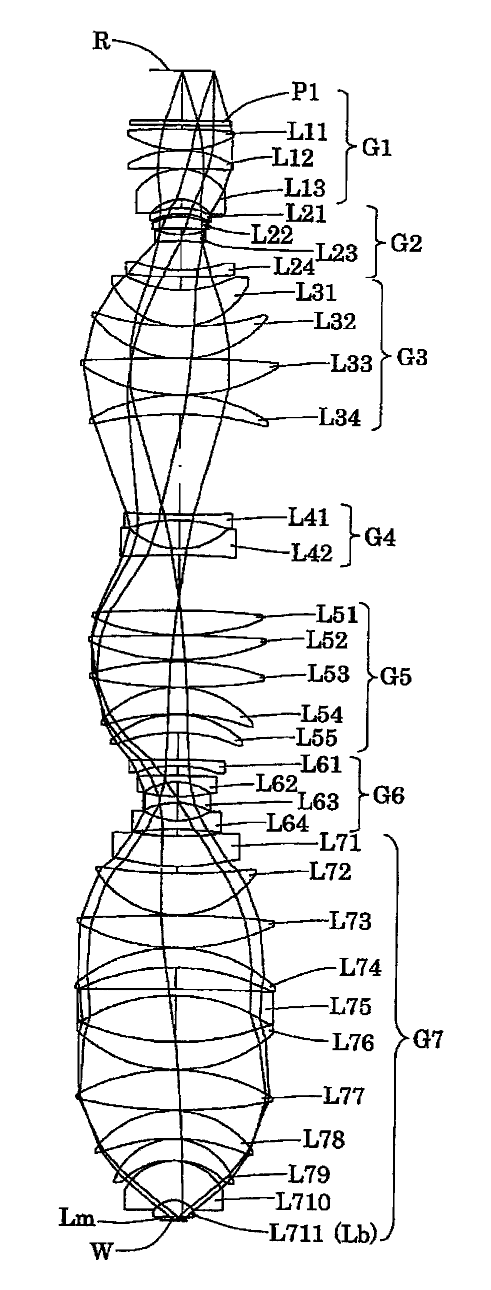
[0050]FIG. 4 is a diagram showing a lens structure of a projection optical system according to a first example of the present embodiment. Referring to FIG. 4, the projection optical system PL of the first example includes, sequentially from the reticle side, a first lens group G1 having positive refractive power, a second lens group G2 having negative refractive power, a third lens group G3 having positive refractive power, a fourth lens group G4 having negative refractive power, a fifth lens group G5 having positive refractive power, a sixth lens group G6 having negative refractive power, and a seventh lens group G7 having positive refractive power. The seven-group structure and the refractive power layout are the same in second and third examples, which will be described later.

[0051]The first lens group G1 includes, sequentially from the reticle side, a plane-parallel plate P1, a biconvex lens L11, a positive meniscus lens L12 having a convex surface facing toward the reticle side...

second example

[0059]FIG. 6 is a diagram showing a lens structure of a projection optical system according to a second example of the present embodiment. Referring to FIG. 6, in the projection optical system PL of the second example, the first lens group G1 includes, sequentially from the reticle side, a plane-parallel plate P1, a positive meniscus lens L11 having a concave surface facing toward the reticle side, a negative meniscus lens L12 having a concave surface facing toward the reticle side, and a biconvex lens L13. The second lens group G2, includes, sequentially from the reticle side, a negative meniscus lens L21 having a convex surface facing toward the reticle side, a biconcave lens L22 having an aspherical concave surface facing toward the reticle side, and a negative meniscus lens L23 having a concave surface facing toward the reticle side.

[0060]The third lens group G3 includes, sequentially from the reticle side, a positive meniscus lens L31 having an aspherical concave surface facing...

third example

[0066]FIG. 8 is a diagram showing a lens structure of a projection optical system according to a third example of the present embodiment. Referring to FIG. 8, in the projection optical system PL of the third example, the first lens group G1 includes, sequentially from the reticle side, a plane-parallel plate P1, a positive meniscus lens L11 having a concave surface facing toward the reticle side, a biconvex lens L12, and a negative meniscus lens L13 having a convex surface facing toward the reticle side. The second lens group G2, includes, sequentially from the reticle side, a negative meniscus lens L21 having a convex surface facing toward the reticle side, a meniscus lens L22 having an aspherical convex surface facing toward the reticle side, a negative meniscus lens L23 having a concave surface facing toward the reticle side, and a negative meniscus lens L24 having a concave surface facing toward the reticle side.

[0067]The third lens group G3 includes, sequentially from the retic...


PUM


Abstract

A refractive projection optical system in which a large image side numerical aperture can be ensured by interposing liquid in the optical path to the image plane, and an image having good planarity can be formed while suppressing radial upsizing. The projection optical system comprising a first image forming system arranged in the optical path between a first plane (R) and a point optically conjugate to a point on the optical axis of the first plane, and a second image forming system arranged in the optical path between the conjugate point and a second plane. In the projection optical system, all optical elements having power are refractive optical elements. The optical path between the projection optical system and the second plane is fillable with liquid having a refractive index larger than 1.3.

Description

CROSS-REFERENCE TO RELATED APPLICATIONS[0001]This application is a continuation of PCT application number PCT / JP2007 / 055238 filed on Mar. 15, 2007.BACKGROUND OF THE INVENTION[0002]One embodiment of the present invention relates to a projection optical system, an exposure apparatus, and a device manufacturing method, and more particularly, to a projection optical system optimal for use in an exposure apparatus employed for manufacturing a device such as a semiconductor element or a liquid crystal display element in a photolithography process.[0003]In a photolithography process for manufacturing a semiconductor element or the like, an exposure apparatus is used to project and expose a pattern image of a mask (or reticle) on a photosensitive substrate (wafer, glass plate, or the like that is coated with photoresist) via a projection optical system. In an exposure apparatus, the projection optical system is required to have a higher resolving power (resolution) as integration of semicon...

Claims


Application Information

Patent Timeline
Patent Type & Authority Applications(United States)
IPC IPC(8): G03B27/54G02B9/64
CPCG02B13/143G02B13/22G03F7/70341G03F7/70241G02B13/24G03F7/70433G03F7/7055
Inventor OHMURA, YASUHIRO
Owner NIKON CORP
Why Eureka
Try Eureka