Water treatment system

a technology of water treatment system and water permeation rate, which is applied in the direction of sedimentation settling tank, multi-stage water/sewage treatment, separation process, etc., can solve the problems of unsatisfactory discharge of wastewater containing infectious microorganisms, decrease of water permeation rate and water treatment capacity, and undesirable discharge of wastewater , to achieve the effect of reducing water purification cost, efficient disinfection of drainage, and improving the effective utilization ratio of raw water

Active Publication Date: 2009-07-02
KK TOSHIBA
View PDF9 Cites 31 Cited by
  • Summary
  • Abstract
  • Description
  • Claims
  • Application Information

AI Technical Summary

Benefits of technology

[0012]The present invention has been made to solve the above-described problems, and is intended to provide a water treatment system for efficiently disinfecting drainage produced by backwashing during filtration membrane treatment to produce reusable water, thereby reducing the cost of water purification and improving the effective utilization ratio of raw water.

Problems solved by technology

However, when water treatment equipment including a filtration membrane is operated for a long time, suspended solids in raw water adhere to the surface of the filtration membrane, which results in the decrease of the water permeation rate and water treatment capacity.
More specifically, accumulation of solid contents and microorganisms (for example, Cryptosporidium, Giardia, fish eggs, algae, and Escherichia coli) increases the filtration pressure, which results in the decrease of the treatment capacity.
Such discharge of wastewater containing infectious microorganisms is undesirable because it can cause recontamination of river water and others.
In addition, water filtered through a filtration membrane is often used for backwashing, so that the discharge of drainage used for backwashing is undesirable from the viewpoint of effective utilization of raw water.
However, the above-described disinfection methods for washing drainage described in Patent Documents 1 and 2 present the following problems.
Under the method described in Patent Document 1, the concentration of the suspended solids containing infectious microorganisms in the concentrated water is so high that transmission of ultraviolet light is inhibited, which results in the deterioration of the disinfection efficiency to inhibit reliable disinfection treatment.
Under the method described in Patent Document 2, suspended solids containing infectious microorganisms after separation and concentration with a filtration membrane are contained in the washing drainage at high concentrations, so that transmission of ultraviolet light through the water is inhibited, and the treated water is discharged in an insufficiently disinfected state, which may results in incomplete prevention of recontamination of rivers and the like.
In addition, under the method, the drainage used for washing a filtration membrane is wholly discharged, which is undesirable from the viewpoint of effective utilization of water resources.

Method used


Image

  • Water treatment system
  • Water treatment system
  • Water treatment system

Examples


first embodiment

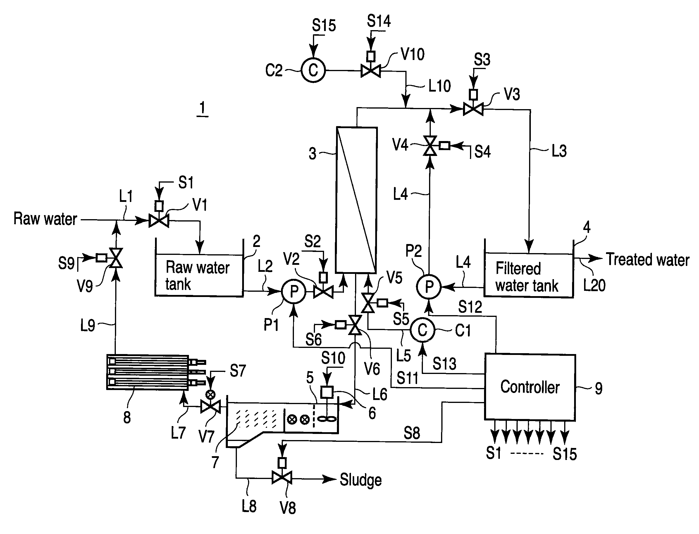
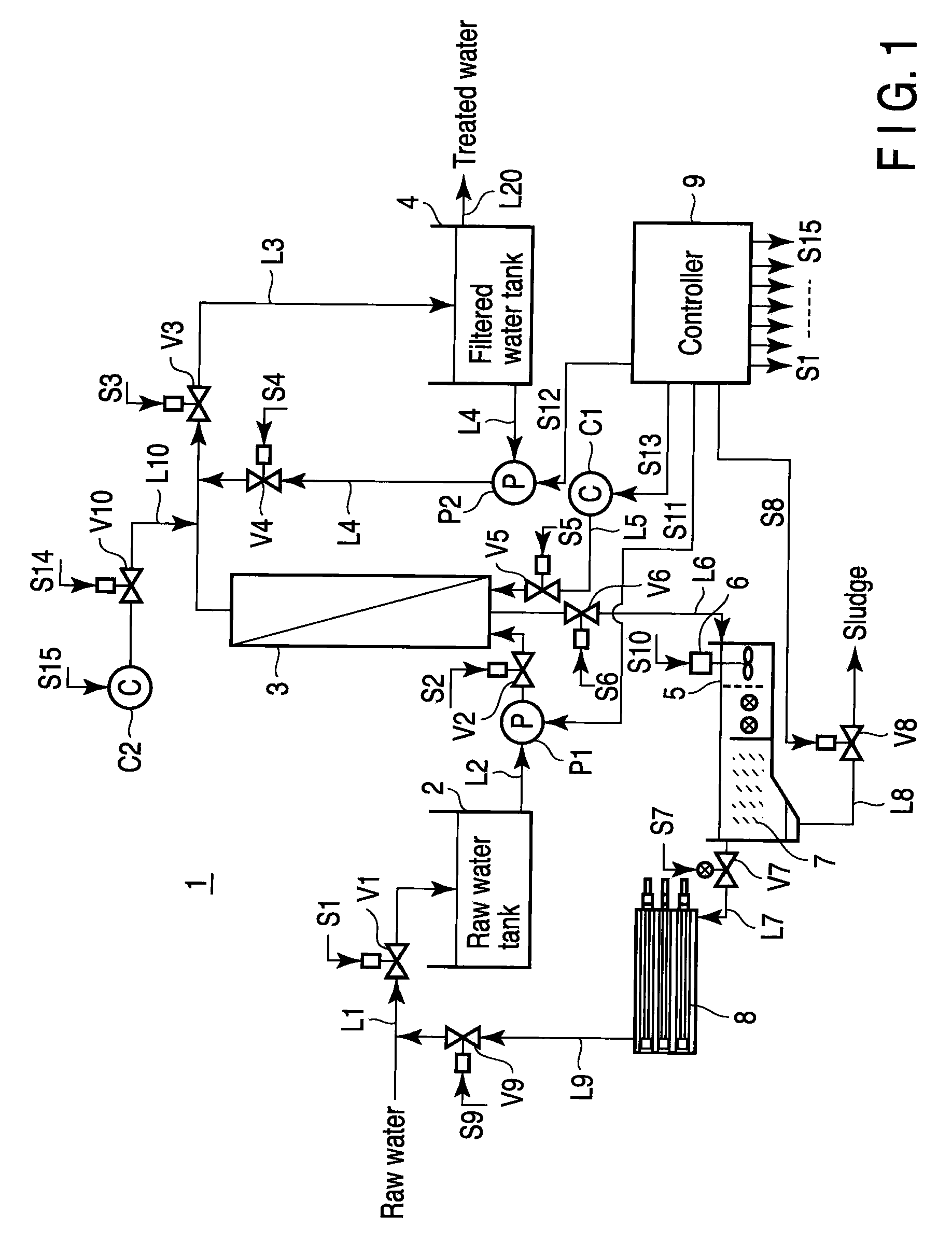
[0037]As shown in FIG. 1, a water treatment system 1 of the first embodiment includes a raw water tank 2, a membrane module 3, a filtered water tank 4, a flocculation tank 5, a the stirrer 6, a precipitator 7, an ultraviolet irradiation reactor 8, and a controller 9.

[0038]The raw water tank 2 is a reserve tank connected to a raw water supply source (not shown) via a line L1. The raw water to be treated (for example, river water) flows into the raw water tank 2 through the line L1. The raw water introducing line L1 has a flow rate control valve V1 controlled by the controller 9. A water outlet is provided at the bottom or near the bottom of the raw water tank 2. The water outlet communicates with the bottom of the membrane module 3 via a line L2. The line L2 has a feed pump (operation pump) P1 which feeds raw water from the raw water tank 2 to the membrane module 3. The line L2 has an on-off valve V2 which is controlled by the controller 9.

[0039]The membrane module 3 includes a filtr...

second embodiment

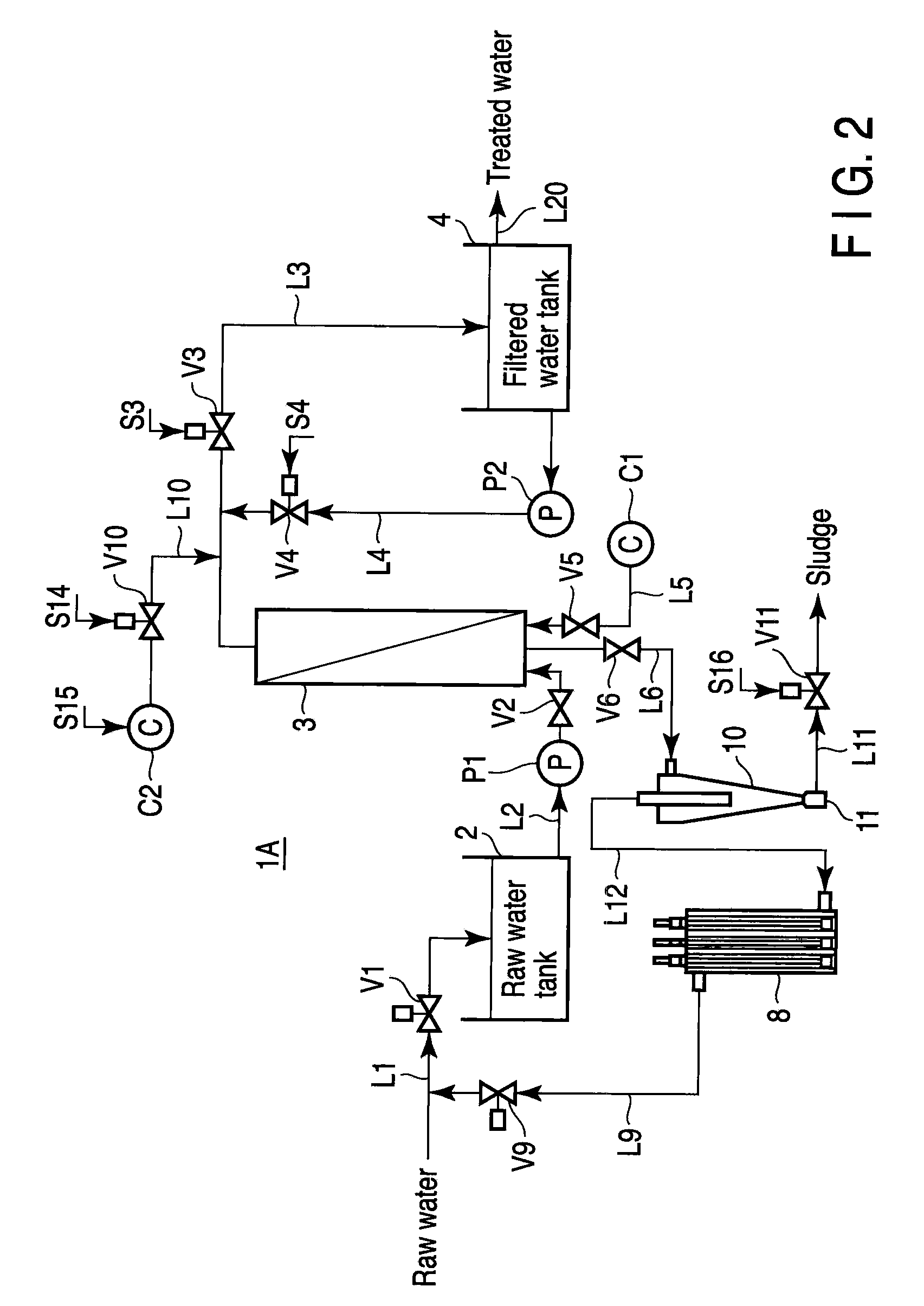
[0067]In the next place, the water treatment system according to a second embodiment of the present invention is described with reference to FIG. 2. Explanations of overlaps between the present embodiment and the above-described embodiment are omitted.

[0068]The system 1A in the present embodiment is different from the system 1 in the first embodiment in that a cyclonic solid-liquid separation device 10 is provided at the drainage treatment line L6 in place of the flocculation tank 5 and precipitator 7. The cyclonic solid-liquid separation device 10 is a centrifuge for physically and mechanically separating suspended solids in the sewage into solid and liquid components.

[0069]The inlet opened at the upper side of the cyclonic solid-liquid separation device 10 communicates with the drainage treatment line L6, into which the drainage from the membrane module 3 flows. The lowest portion of the cyclonic solid-liquid separation device 10 has a sludge collection vessel 11. The sludge colle...

third embodiment

[0075]The water treatment system according to a third embodiment of the present invention is described below with reference to FIG. 3. Explanations of overlaps between the present embodiment and the above-described embodiment are omitted.

[0076]The water treatment system 1B in the present embodiment is different from the system 1A in the second embodiment in that a cyclonic ultraviolet irradiation reactor 13 including ultraviolet lamps in a cyclonic solid-liquid separation device is provided at the drainage treatment line L6 in place of the cyclonic solid-liquid separation device 10 and ultraviolet irradiation drainage 8. The cyclonic ultraviolet irradiation reactor 13 is a centrifuge for physically centrifuging suspended solids in the sewage into solid and liquid components, and at the same time, irradiating microorganisms in the drainage with ultraviolet light for disinfection. The cyclonic ultraviolet irradiation reactor 13 is substantially the same as the apparatus disclosed in F...


PUM

PropertyMeasurementUnit
wavelengthaaaaaaaaaa
diameteraaaaaaaaaa
lengthaaaaaaaaaa

Abstract

Disclosed is a water treatment system including a raw water tank, a module which includes a filtration membrane, a feed pump, a filtered water tank, a backwash pump which flows filtered water backward from the filtered water tank to the module, a valve and a channel which switch the direction of the water flow between the forward and reverse directions, a controller which suspends the supply of raw water from the raw water tank to the module, switches the valve and channel to the reverse direction, makes the backwash pump to supply filtered water from the filtered water tank to the module thereby backwashing the filtration membrane, and washing drainage treatment line including which treats backwashing drainage generated by backwashing of the filtration membrane, and returns the water to the raw water tank.

Description

CROSS-REFERENCE TO RELATED APPLICATIONS[0001]This application is based upon and claims the benefit of priority from prior Japanese Patent Application No. 2007-338201, filed Dec. 27, 2007, the entire contents of which are incorporated herein by reference.BACKGROUND OF THE INVENTION[0002]1. Field of the Invention[0003]The present invention relates to a method for disinfecting drainage used for washing filtration membranes for purifying raw water such as groundwater or river water.[0004]2. Description of the Related Art[0005]Heretofore, in order to produce tap water or industrial water from raw water such as river water, lake water, and groundwater, filtration membranes have been widely used on their merits such as reliability and automatic operation. However, when water treatment equipment including a filtration membrane is operated for a long time, suspended solids in raw water adhere to the surface of the filtration membrane, which results in the decrease of the water permeation rat...

Claims


Application Information

Patent Timeline
Patent Type & Authority Applications(United States)
IPC IPC(8): B01D35/22B01D33/50
CPCB01D61/18C02F2209/42B01D65/02B01D65/027B01D2321/00B01D2321/04C02F1/32C02F1/38C02F1/444C02F1/5236C02F2209/006C02F2209/02C02F2209/03C02F2209/11C02F2209/40B01D61/22B01D2321/44
Inventor ABE, NORIMITSUMURAYAMA, SEIICHIIDE, TAKESHIMORIKAWA, AKIRATAMAKI, SHOJIRO
Owner KK TOSHIBA
Why Eureka
Try Eureka