
Method for Producing Surfaces and Materials by Laser Ablation

a laser ablation and surface technology, applied in the field of laser ablation-based coating methods, can solve the problems of high cost, high vacuum level, and inability to achieve effective and high-quality coating of three-dimensional objects, and achieve the effects of low cost, high quality and good repeatability

Inactive Publication Date: 2009-07-02
PICODEON OY
View PDF36 Cites 17 Cited by
  • Summary
  • Abstract
  • Description
  • Claims
  • Application Information

AI Technical Summary

Benefits of technology

[0047]The present invention enables the manufacturing of any planar or three-dimensional surface or even a 3D object with a high quality, economically and industrially feasibly.
[0049]The present invention is based on the surprising observation that both planar and particularly three-dimensional geometric objects can be coated with excellent technical features (surface uniformity, coarseness features, hardness and when needed, also optical features and crystal structure) and industrially feasible production rates. It is particularly advantageous to produce surfaces so that the distance between the target material to be ablated and the substrate to be coated is kept sufficiently short, i.e. within the range 2 μm-20 mm.
[0056]A fourth object of the invention is to achieve at least a novel method and / or connected means for solving the problem how to create by means of high-quality plasma a coating with good adhesion features for gripping the substrate, so that the wasting of kinetic energy in the particle-like fragments is reduced by restricting the occurrence of the fragments or by restricting their size to be smaller than the ablation depth. At the same time, owing to their absence, the fragments do not create cool surfaces that could affect the homogeneity of the plasma jet through the phenomena of nucleation and condensation. Moreover, according to the fourth object, the radiation energy is effectively transformed to plasma energy, as the area affected by heating is minimized when using advantageously short radiation pulses, in other words pulses of the picosecond order or even shorter duration, and in between the pulses, there is applied a certain interval in between two successive pulses.
[0062]When using a surface treatment apparatus according to an embodiment of the invention, the removal of material from the surface to be treated and / or the generation of coating can be raised up to a level that is required of a high-quality coating, even at a sufficient production speed without unnecessary restrictions to the radiation power.
[0064]Embodiments of the invention can be used to make products and / or coatings where the materials of the product can be chosen rather freely. For example, semiconductor diamond can be produced, but in a manner of mass production, very large amounts, with low cost, good repeatability and in high quality.

Problems solved by technology
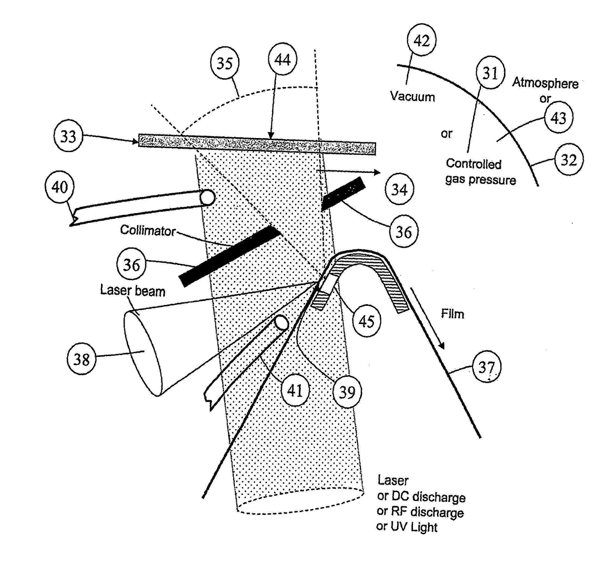
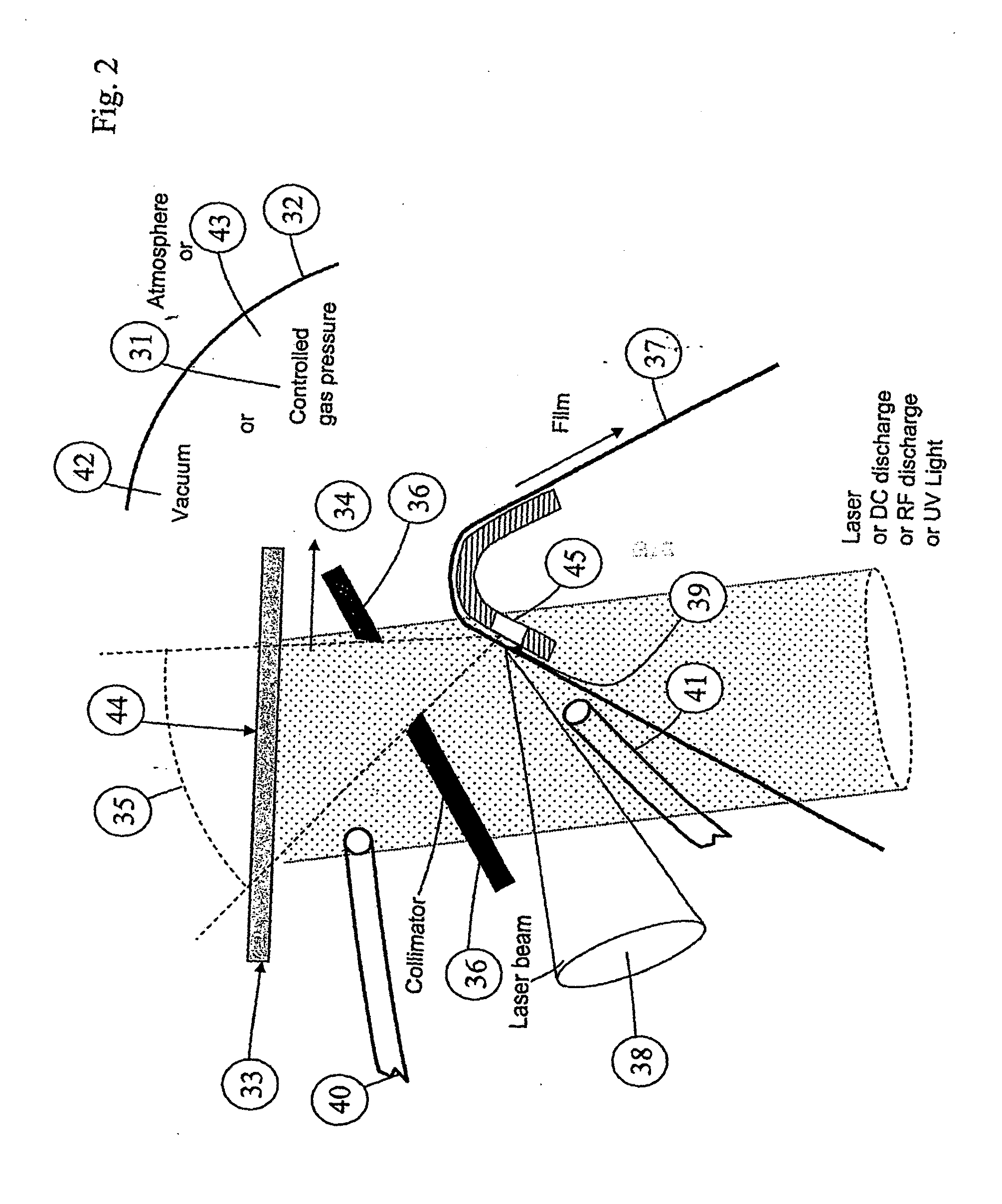
Current coating methods based on laser ablation do not allow an effective and high-quality coating of three-dimensional objects, for example.
In addition, in order to reasonably succeed in coating even small planar surfaces, current methods require the use of high, expensive vacuum levels, typically a vacuum of the order of 10−5-10−6 mbar at most.

Method used


Image

  • Method for Producing Surfaces and Materials by Laser Ablation
  • Method for Producing Surfaces and Materials by Laser Ablation
  • Method for Producing Surfaces and Materials by Laser Ablation

Examples


example 1

[0170]In this example, marble was coated by a diamond coating (of sintered carbon). The performance parameters of the laser apparatus were as follows: repetition frequency 4 MHz, pulse energy 5 μJ, pulse length 20 pS, distance between target and substrate 4 mm, and vacuum level: 10−3 mbar (10−6 atmospheres). The created diamond surface was examined by AFM equipment (Atomic Force Microscope). The diamond surface thickness was roughly 500 nm, and the surface uniformity ±10 nm. Microparticles were not observed on the surface.

example 2

[0171]In this example, an aluminum film was coated by diamond coating (of sintered carbon). The performance parameters of the laser apparatus were as follows: repetition frequency 4 MHz, pulse energy 5 μJ, pulse length 20 ps, distance between target and substrate 4 mm, and vacuum level: 10−5 atmospheres. The aluminum film was colored in a sky-blue shade. The created diamond surface was examined by an AFM equipment (Atomic Force Microscope). The diamond surface thickness was roughly 200 nm, and the surface uniformity ±8 nm. Microparticles were not observed on the surface.

example 3

[0172]In this example, a silicon dioxide object was coated with diamond coating. The performance parameters of the laser apparatus were as follows: repetition frequency 2 MHz, pulse energy 10 μJ, pulse length 15 ps, distance between target and substrate 2 mm, and vacuum level: 10−3 atmospheres. The created diamond surface was examined by AFM equipment (Atomic Force Microscope). The diamond surface thickness was roughly 50 nm, and the surface uniformity ±4 nm. Microparticles were not observed on the created surface. The surface coarseness was excellent, and the nano particle size was at most 20 nm.


PUM

PropertyMeasurementUnit
diameteraaaaaaaaaa
sizeaaaaaaaaaa
sizeaaaaaaaaaa

Abstract

The invention relates to a laser ablation coating method, where the laser ablation is carried out in a space with 10−3 atmospheres at most. A low vacuum level enables an advantageous industrial production of surfaces without remarkably weakening the quality features of the deposited surfaces. The invention also relates to a method for producing nano particles, so that target material is ablated by pulse laser for generating nano particles in a space with 10−3 atmospheres at most.

Description

FIELD OF THE INVENTION[0001]The present invention relates to a coating method based on laser ablation and a method for simultaneously producing nano particles, in which method there are produced either high-quality surfaces or nano particles either in a vacuum, in normal air pressure or in overpressure.PRIOR ART[0002]Laser technology has advanced significantly in the recent years and now it is possible to produce fiber-based semiconductor laser systems with a tolerable efficiency that can be used in cold ablation, for example. Among these lasers meant for cold working are picosecond lasers and femtosecond lasers. For instance in picosecond lasers, the cold working range refers to pulse lengths where the pulse length is 100 picoseconds or less. In addition to pulse length, picosecond lasers differ from femtosecond lasers with respect to the repetition frequency; the repetition frequencies of latest commercial picosecond lasers are 1-4 MHz, whereas femtosecond lasers remain in the rep...

Claims


Application Information

Patent Timeline
Patent Type & Authority Applications(United States)
IPC IPC(8): B23K26/36
CPCB23K26/12B23K26/122B23K26/123B23K26/365C23C14/28C23C14/081C23C14/083C23C14/086C23C14/087C23C14/0611B23K26/1224B23K26/361B82B3/00C23C14/00
Inventor LAPPALAINEN, REIJOMYLLYMAKI, VESAPULLI, LASSEMAKITALO, JUHA
Owner PICODEON OY
Learn More