Device for detecting electromagnetic radiation and ionizing radiation having an isotropic transfer layer

a technology of which is applied in the field of devices for detecting electromagnetic radiation and ionizing radiation, can solve the problems of reducing the ratio of coherent signal to undesirable noise, reducing the resolution and sensibility of the sensor operating according to this first principle, and reducing the resolution and sensibility of the sensor to low exposure dose. , to achieve the effect of simple, robust and efficient, and optimizing performan

Inactive Publication Date: 2009-07-02
COMMISSARIAT A LENERGIE ATOMIQUE ET AUX ENERGIES ALTERNATIVES
View PDF9 Cites 4 Cited by
  • Summary
  • Abstract
  • Description
  • Claims
  • Application Information

AI Technical Summary

Benefits of technology

[0033]The present invention serves, in particular, to solve the technical problems discussed above by proposing a configuration of a sensor of radiation, particularly X-rays or γ rays, with direct conversion, offering a simple, robust and efficient method for fabricating large imagers, typically larger than 10×10 cm, and furthermore, not using the costly techniques of methods such as photolithography....

Problems solved by technology

However, in a manner known per se, the sensors operating according to this first principle have limited performance in terms of resolution and sensibility to low exposure dose.
In a manner known per se, these inter-pixel leakage currents or leakage currents within the sensing layer 11 cause a degradation of the image quality, that is, a lowering of the ratio of the coherent signal to the undesirable noise.
This degradation must, whenever possible, be offset by a complex and therefore costly image processing.
In fact, the precision required for the batching and positioning of the pads 15 often proves to be difficult to obtain and always sharply increases the production cost of the sensor, regardless of the technique employed (screen-printing, dispense, etc.).
Moreover, this type of connection does not allow f...

Method used


Image

  • Device for detecting electromagnetic radiation and ionizing radiation having an isotropic transfer layer
  • Device for detecting electromagnetic radiation and ionizing radiation having an isotropic transfer layer
  • Device for detecting electromagnetic radiation and ionizing radiation having an isotropic transfer layer

Examples


Embodiment Construction

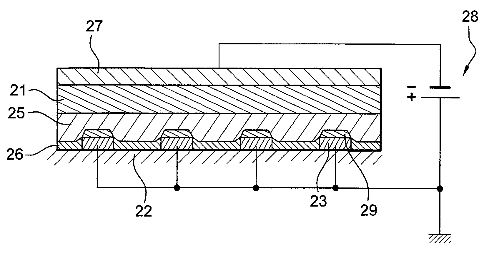
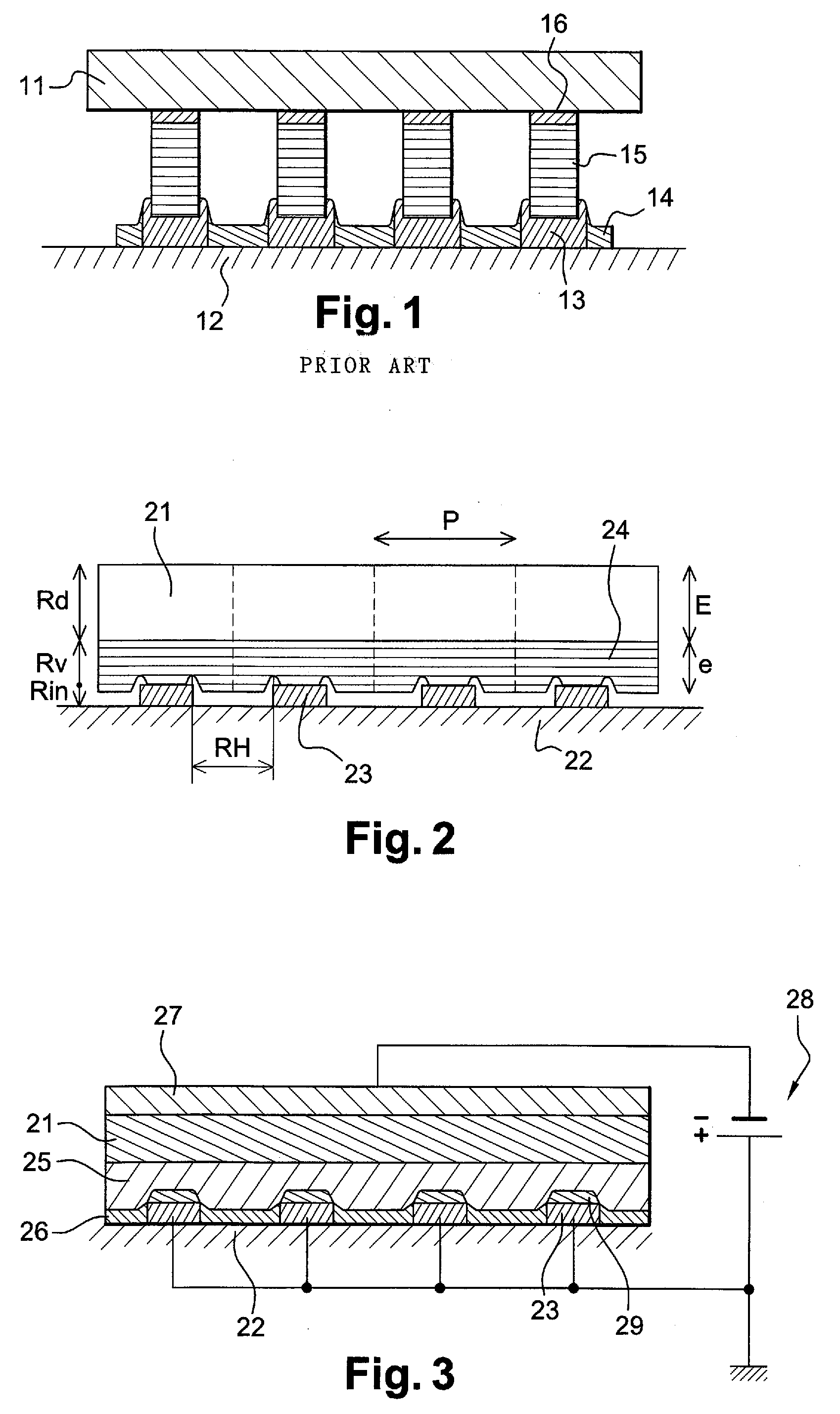
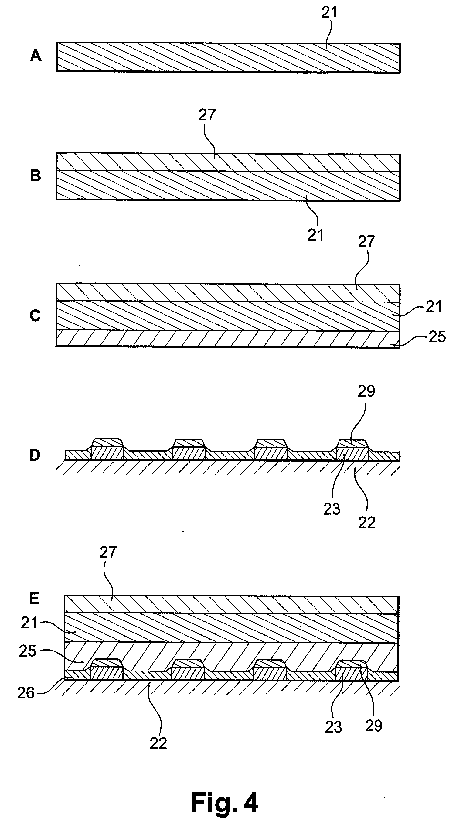
[0056]FIG. 3 shows a device for detecting electromagnetic radiation and ionizing radiation according to the invention. In the present case, this device is more particularly intended for detecting X-rays or γ rays, but the present invention may also apply to the detection of electromagnetic radiation having different energy spectra or charged particles.

[0057]According to the invention, the sensor comprises a sensing layer 21 also called photodetector, consisting of one or more materials capable of interacting with the incident rays, in order to liberate mobile charge carriers. These mobile charge carriers may be electrons or holes, and therefore carry negative or positive charges.

[0058]In a manner known per se, the travel of these mobile charge carriers, under the action of a bias voltage 28, generates electric currents, of which the strength is representative of the energy deposited by the incident rays and, hence, of the scene observed.

[0059]After this direct conversion step in the...


PUM


Abstract

This device for detecting electromagnetic radiation, in particular X-ray or γ-rays, includes: a sensing layer consisting of at least one material capable of interacting with said electromagnetic radiation to be detected, in order to liberate mobile charge carriers, whereof the movement generates an electric current; a substrate provided with a plurality of elementary collectors of the charge carriers thus liberated, said elementary collectors being distributed discretely; a transfer layer suitable for transferring the charge carriers liberated by the sensing layer at the elementary collectors, said layer being connected to the sensing layer; and an insulating adhesive mating layer, suitable for mating the plurality of elementary collectors and the transfer layer.

Description

CROSS REFERENCE TO RELATED APPLICATIONS[0001]This application claims priority under 35 U.S.C. §119 from French Patent Application No. 0760454 filed on Dec. 31, 2007 in the French Patent Office, the entire disclosure of which is incorporated herein by reference.FIELD OF THE INVENTION[0002]The present invention relates to a device for detecting electromagnetic radiation, and ionizing radiation, in particular X-rays and / or γ rays. The present invention therefore relates to the field of sensors, whether they are matrix sensors having one or two dimensions or other forms of sensors.[0003]The present invention relates more specifically to the structure for electric interconnection and mating between the components of such a sensor.BACKGROUND OF THE INVENTION[0004]In the field of sensors designed to produce digital images, the prior art contains two different principles for converting the electromagnetic rays to electrons and, hence, to digital signals. The first of these two principles, c...

Claims


Application Information

Patent Timeline
IPC IPC(8): G01T1/16
CPCH01L27/14676H01L31/085H01L31/0296H01L27/14696
Inventor GASSE, ADRIENARQUES, MARCMATHIEU, LYDIEBRAMBILLA, ANDREA
Owner COMMISSARIAT A LENERGIE ATOMIQUE ET AUX ENERGIES ALTERNATIVES
Why Eureka
Try Eureka