Testing method of wavelength-tunable laser, controlling method of wavelength-tunable laser and laser device
a wavelength-tunable laser and control method technology, applied in the direction of optical radiation measurement, instruments, semiconductor lasers, etc., can solve the problems of limiting the growth of size and the increase of cost, and achieve the stability of the operating point of wavelength selection properties, the effect of restrainting the enlargement of the component count and assembly hour
- Summary
- Abstract
- Description
- Claims
- Application Information
AI Technical Summary
Benefits of technology
Problems solved by technology
Method used
Image

Examples
first embodiment
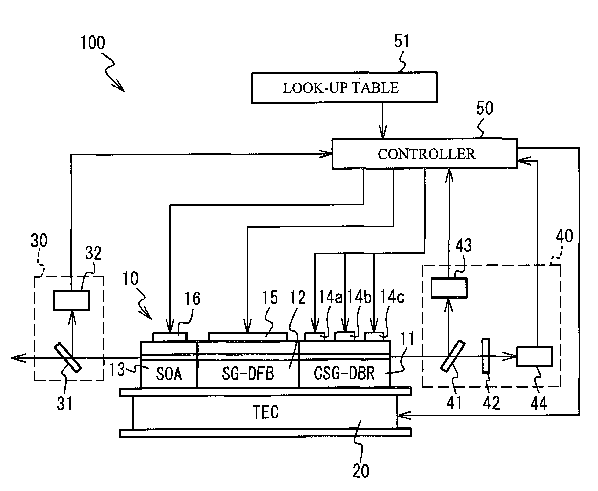
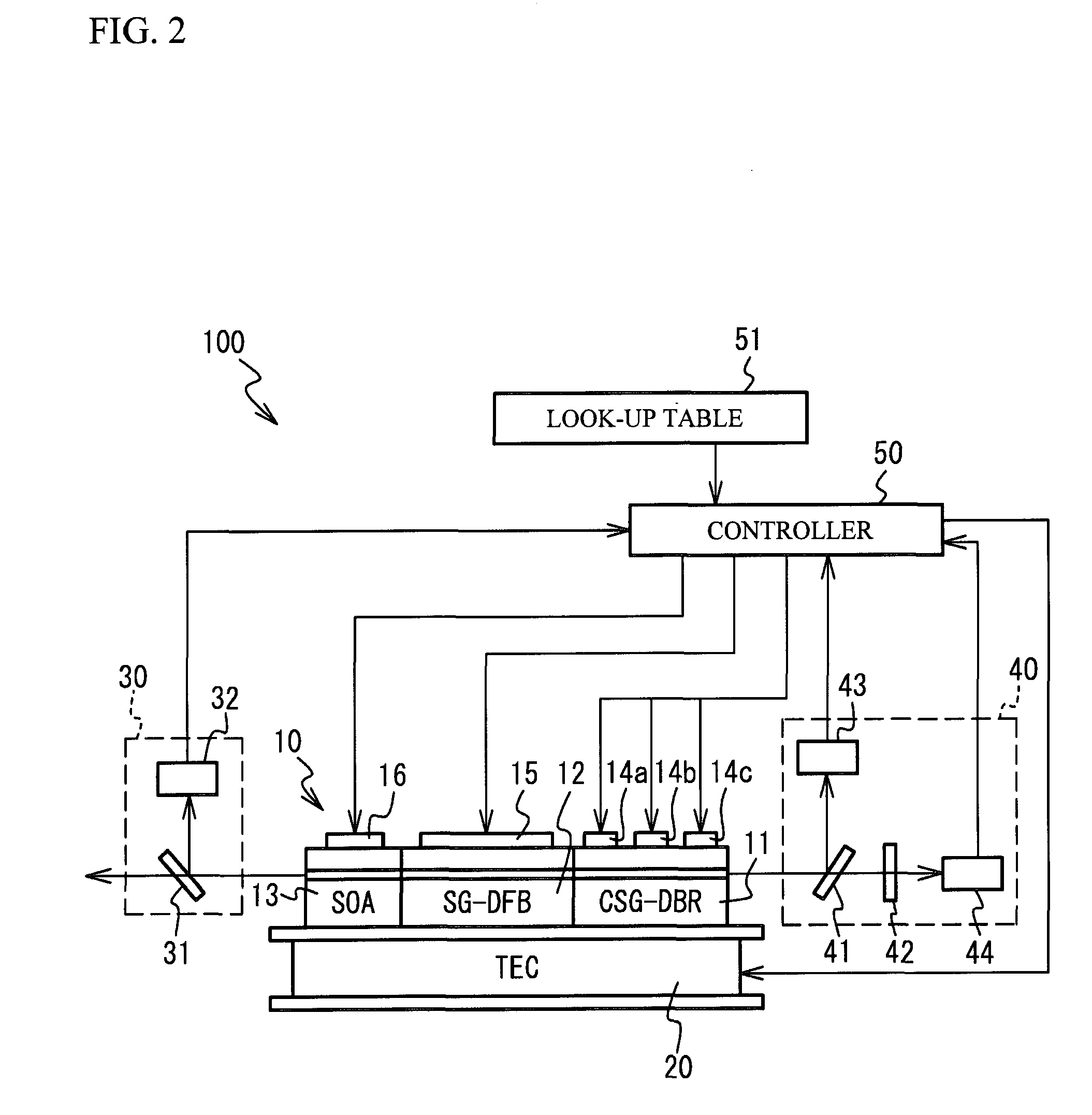
[0045]FIG. 2 illustrates a schematic view of a wavelength-tunable laser 10 in accordance with a first embodiment and a laser device 100 having the wavelength-tunable laser 10. As illustrated in FIG. 2, the laser device 100 has the wavelength-tunable laser 10, a temperature control device 20, an output detector 30, a wavelength detector 40 and a controller 50. The wavelength-tunable laser 10 is on the temperature control device 20. A description will be given of details of each component.
[0046]The wavelength-tunable laser 10 has a structure in which a Chirped Sampled Grating Distributed Reflector (CSG-DR) region 11, a Sampled Grating Distributed Feedback Laser (SG-DFB) region 12 and a Semiconductor Optical Amplifier (SOA) region 13 are coupled in order.
[0047]The CSG-DBR region 11 has an optical waveguide having segments in which a first region having a diffraction grating and a second region coupled to the first region and acting as a spacer are provided. In the embodiment, three seg...
second embodiment
[0139]FIG. 16 illustrates a schematic view of a laser device 100a in accordance with a second embodiment. The laser device 100a is different from the laser device 100 in a point that a wavelength-tunable laser 10a is provided instead of the wavelength-tunable laser 10.
[0140]As illustrated in FIG. 16, the wavelength-tunable laser 10a has a structure in which a SG-DBR (Sampled Grating Distributed Bragg Reflector) region 21, a PS (Phase Shift) region 22, a Gain region 23, a SG-DBR region 24 and the SOA region 13 are coupled in order.
[0141]The SG-DBR regions 21 and 24 have an optical waveguide having segments in which a first region having a diffraction grating and a second region coupled to the first region and acting as a spacer are provided. The optical waveguide is made of semiconductor crystalline having an absorption edge wavelength at shorter wavelengths side compared to the laser oscillation wavelength. Each second region has a length equal to each other in the SG-DBR regions 21...
third embodiment
[0145]FIG. 17 illustrates a schematic view of a laser device 100b in accordance with a third embodiment. As illustrated in FIG. 17, the laser device 100b has a Gain element 10b composed of a Gain region 61 and a PS region 62. There are provided a fixed etalon 67 and a liquid crystal mirror 66 in order on the PS region 62 side of the Gain element 10b. The fixed etalon 67 is an optical etalon having periodical transparent wavelength peak. The liquid crystal mirror 66 has a structure in which a liquid crystal etalon is integrated with a mirror for forming a resonator between the mirror and the edge face of the Gain region 61. Here, the liquid crystal etalon has an optical etalon structure where a liquid crystal region is sealed, refractive index of the liquid crystal being controllable with voltage. The liquid crystal mirror 66 in accordance with the embodiment has a liquid crystal etalon having wavelength peak different from that of the fixed etalon 67. Peak of reflection wavelength p...
PUM
 Abstract
Description
Claims
Application Information
PatSnap Eureka turns technology decisions into work you can execute. Powered by our Innovation Knowledge Graph, it runs expert workflows across engineering, life sciences, materials and intellectual property. Get your review-ready output in minutes.


