Frequency compensation based on dual signal paths for voltage-mode switching regulators

a voltage-mode switching regulator and frequency compensation technology, which is applied in the direction of dc-dc conversion, climate sustainability, power conversion systems, etc., can solve the problems of reducing the efficiency of voltage-mode switching regulators. , to achieve the effect of improving circuit design

a voltage-mode switching regulator and frequency compensation technology, which is applied in the direction of dc-dc conversion, climate sustainability, power conversion systems, etc., can solve the problems of reducing the efficiency of voltage-mode switching regulators. , to achieve the effect of improving circuit design

US20090174383A1Active Publication Date: 2009-07-09THE HONG KONG UNIV OF SCI & TECH

Image

  • Frequency compensation based on dual signal paths for voltage-mode switching regulators
  • Frequency compensation based on dual signal paths for voltage-mode switching regulators
  • Frequency compensation based on dual signal paths for voltage-mode switching regulators

Examples


Embodiment Construction

[0027]The following examples further illustrate the invention but, of course, should not be construed as in any way limiting its scope.

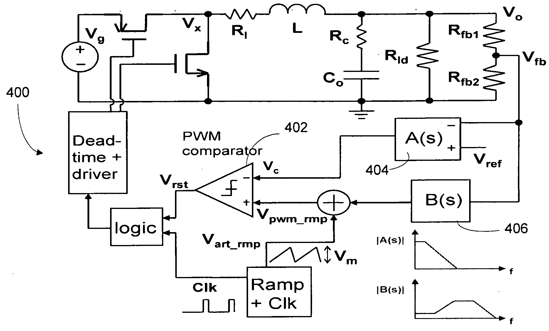
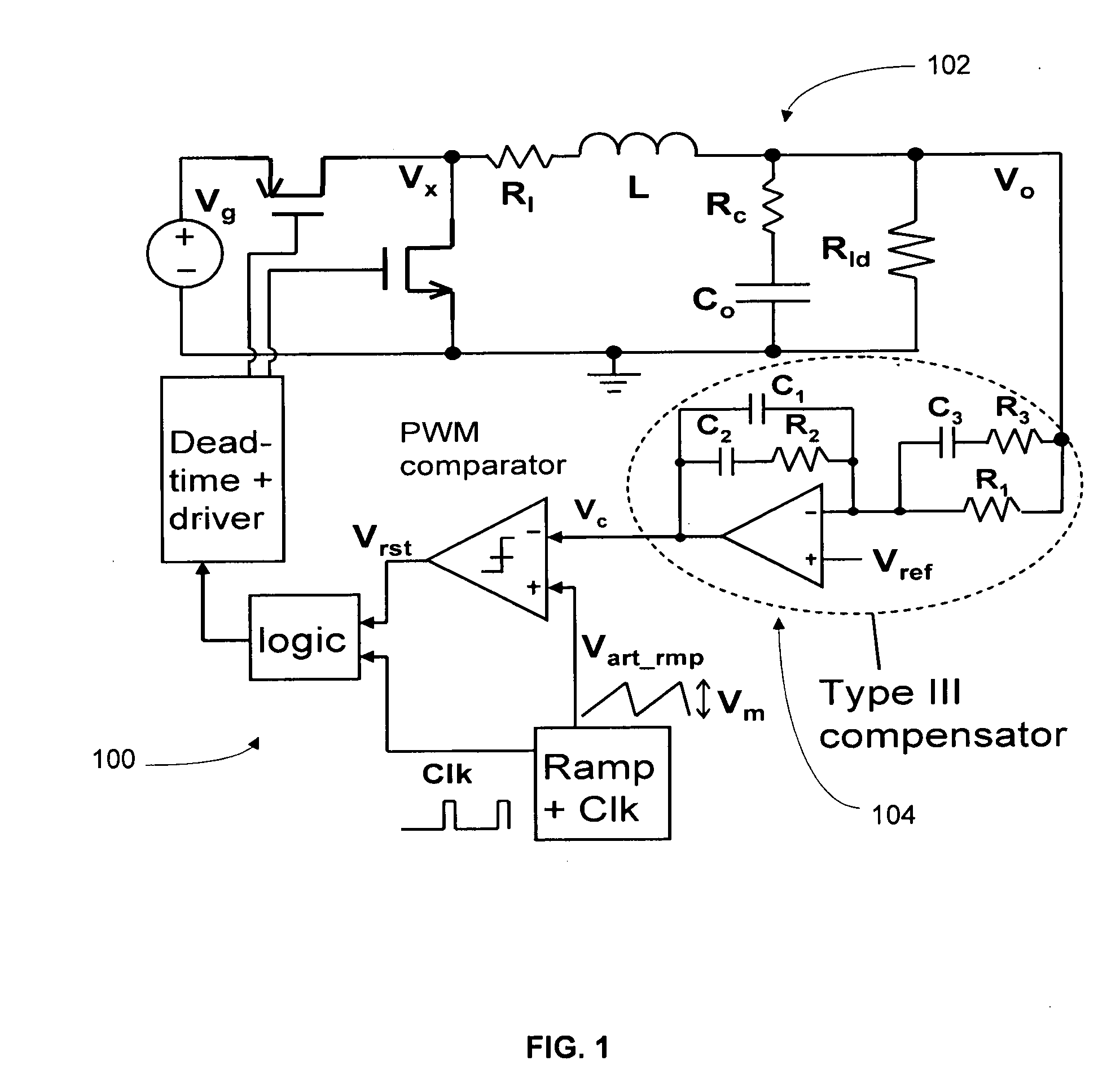
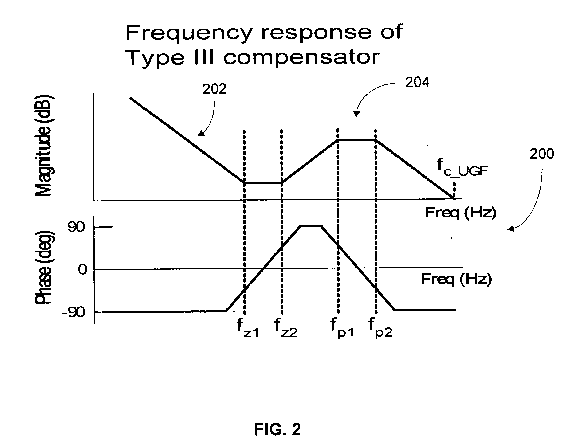
[0028]With reference to FIGS. 1-3, a brief theory of Type III compensation is explained using a Buck converter 100 illustrated in FIG. 1 as an example. Since there is a complex pole due to the L-C output filter 102 of the Buck converter 100, phase lag increases sharply at the complex pole frequency, fLCo. The loop gain crossover frequency must be limited to one-tenth of fLCo to ensure enough phase margin if integrator type compensator (Type I) is used. Type III compensation is often employed to extend the crossover frequency and improve the phase margin of the loop gain. It generates two zeros to provide phase boost and offsets the complex pole phase lag. In this way, the crossover frequency can be extended beyond fLCo (still limited to ˜20% of switching frequency for a robust system).

[0029]FIG. 2 shows the frequency response 200 of a Type III compen...


PUM


Abstract

A frequency compensation method for voltage-mode switching regulators is disclosed. A lowpass filter and a bandpass filter are employed in the two signal paths into the dual inputs of PWM comparators. In one embodiment, two zeros are generated to compensate for the L-C output filter poles. Stable operation, low output voltage ripple and fast load transient response are achieved; while the power consumption of error amplifier and the area for implementing on-chip passive components are greatly reduced.

Description

CROSS-REFERENCE TO RELATED APPLICATIONS[0001]This patent application claims the benefit of U.S. Provisional Patent Application No. 61 / 009,964, filed Jan. 7, 2008, which is incorporated herein by reference in its entirety.FIELD OF THE INVENTION[0002]This invention relates generally to a methodology and circuit for synthesizing appropriate compensation response to linear circuits; and more particularly to switching regulators using dual signal paths into pulse-width modulation (PWM) comparators and a built-in summation function of a PWM comparator.BACKGROUND OF THE INVENTION[0003]Switching regulators are widely used in modern portable devices due to their high power conversion efficiency. Fixed-switching-frequency PWM voltage-mode control and current-mode control are the two main control schemes typically used. Compared to the current-mode control, voltage-mode control has the advantage of less sophisticated control circuitries, lower noise sensitivity, and potentially higher power ef...

Claims


Application Information

Patent Timeline
09 Jul 2009
Publication
US20090174383A1
IPC
G05F1/00
CPC
H02M3/156; Y02B70/1466; H02M3/1588; Y02B70/10
Inventors
TSUI, YIP SUM; WU, YING