
Spark Ignition Type Internal Combustion Engine

a technology of spark ignition and internal combustion engine, which is applied in the direction of electrical control, process and machine control, instruments, etc., can solve the problems of inability to exhibit excellent exhaust purification action, difficult to exhaust exhaust gas from the combustion chamber, and temperature drop of exhaust gas

Inactive Publication Date: 2009-07-16
TOYOTA JIDOSHA KK
View PDF18 Cites 6 Cited by
  • Summary
  • Abstract
  • Description
  • Claims
  • Application Information

AI Technical Summary

Benefits of technology

[0007]Therefore, an object of the present invention is to provide a spark ignition type internal combustion engine able to maintain an exhaust purification catalyst at a relatively high temperature even when operating the internal combustion engine in the state of a large expansion ratio.
[0017]In another aspect of the present invention, the higher the engine speed, the higher the actual compression ratio.
[0020]In another aspect of the present invention, the closing timing of the intake valve is shifted as the engine load becomes lower to a direction away from intake bottom dead center until a limit closing timing enabling control of the amount of intake air fed into the combustion chamber.
[0024]In another aspect of the present invention, in a region of a load lower than the engine load when the closing timing of the intake valve reaches the limit closing timing, the lower the load, the larger the air-fuel ratio is made.
[0028]According to the present invention, since as much exhaust gas as possible is discharged from the combustion chamber to the exhaust purification catalyst, even if operating the internal combustion engine in the state of a large expansion ratio, the exhaust purification catalyst can be maintained at a relatively high temperature.

Problems solved by technology

However, if increasing the expansion ratio in this way, most of the heat energy produced in the combustion chamber is converted to kinetic energy, so the exhaust gas falls in temperature.
Further, along with this, the pressure of the exhaust gas in the combustion chamber at the end of the expansion stroke also becomes lower and accordingly the exhaust gas becomes harder to exhaust from the combustion chamber.
On the other hand, if the engine exhaust purification catalyst provided in the engine exhaust passage is not raised to a certain temperature or more, generally it cannot exhibit its excellent exhaust purification action.
Further, if increasing the expansion ratio, the exhaust gas becomes harder to be exhausted from the combustion chamber, so the flow rate of the exhaust gas flowing into the exhaust purification catalyst becomes smaller.
For this reason, if operating the internal combustion engine in the state of a large expansion ratio, maintaining the exhaust purification catalyst at a high temperature becomes difficult.

Method used


Image

  • Spark Ignition Type Internal Combustion Engine
  • Spark Ignition Type Internal Combustion Engine
  • Spark Ignition Type Internal Combustion Engine

Examples


Embodiment Construction

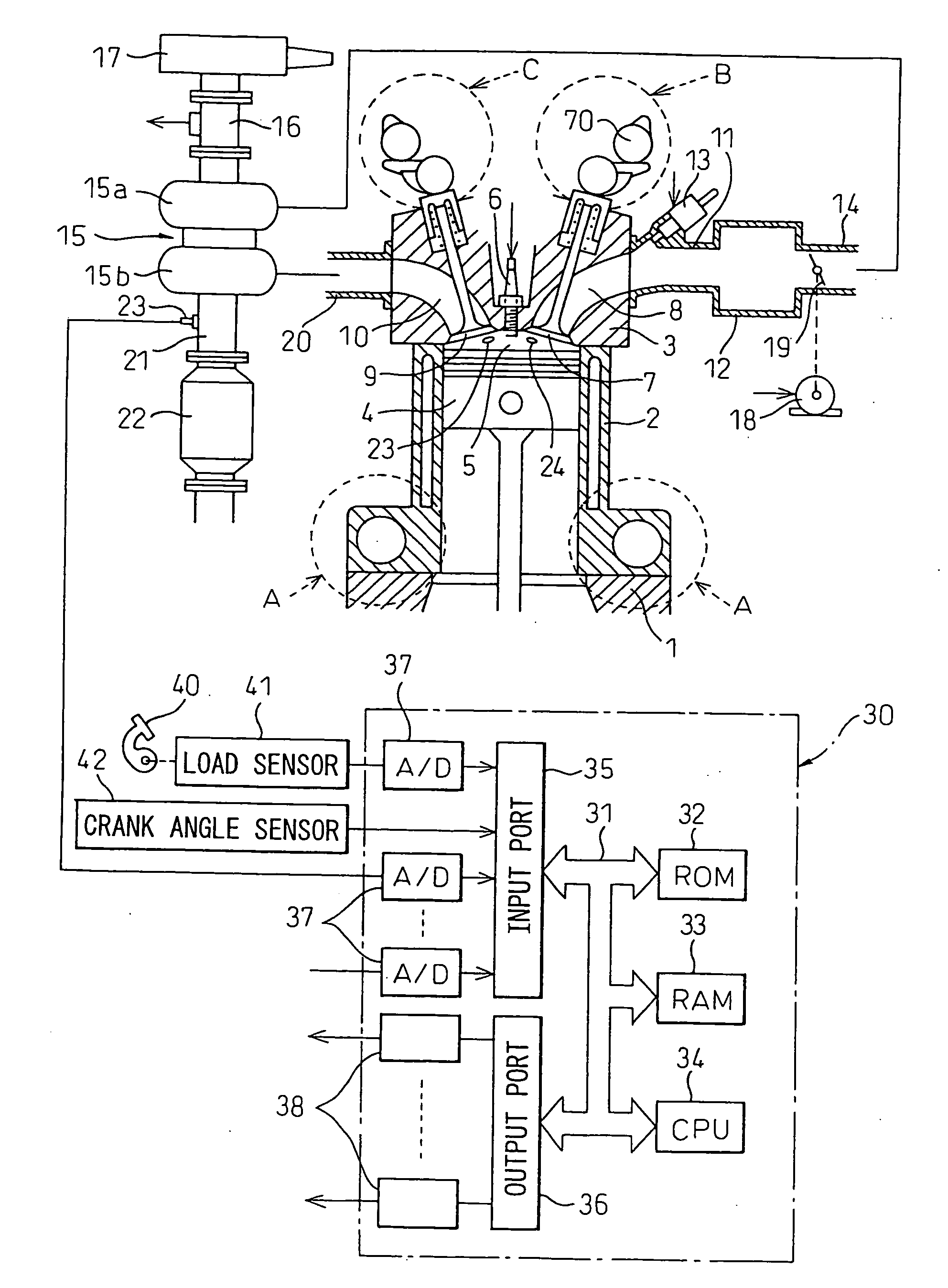
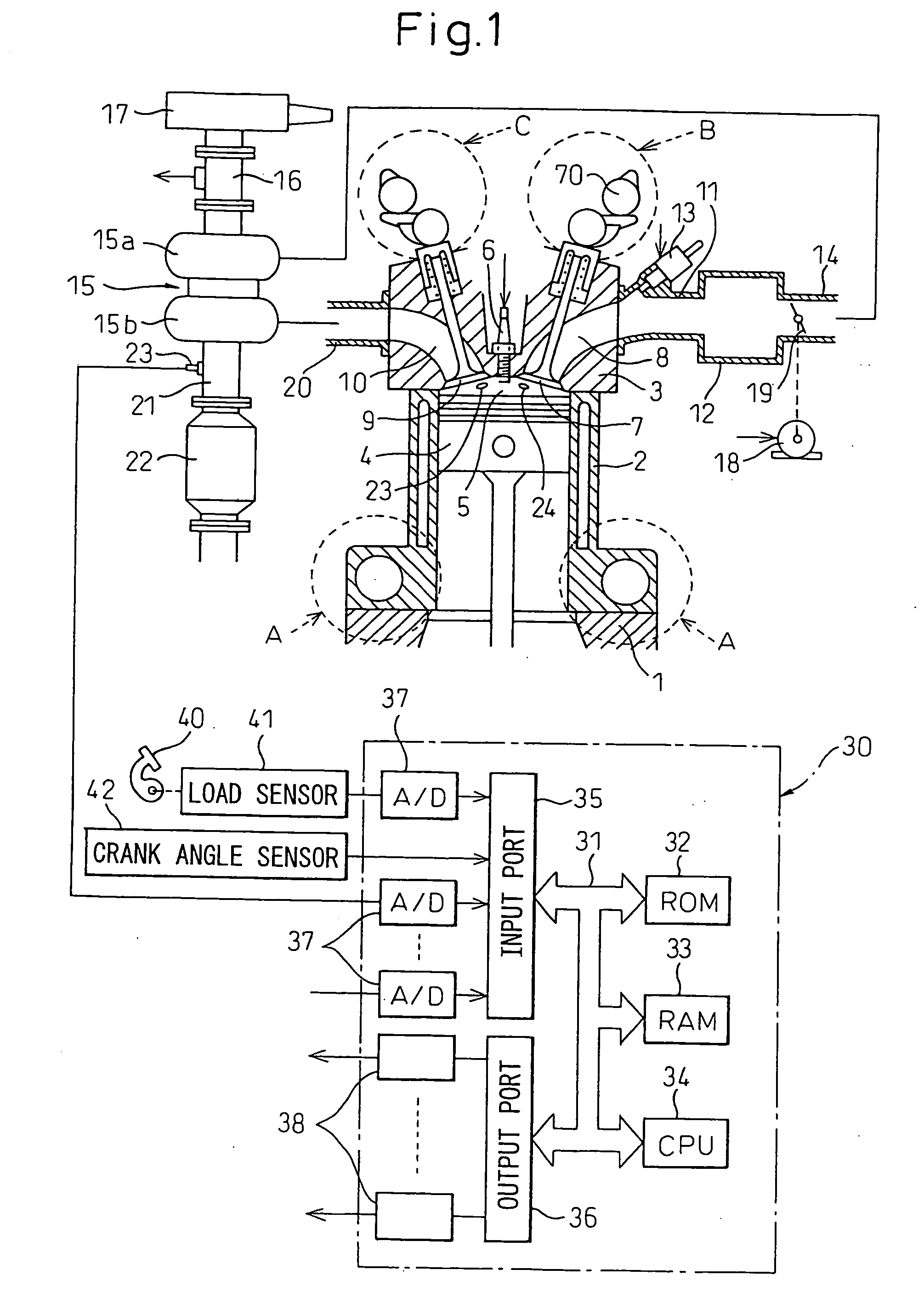
[0045]FIG. 1 shows a side cross-sectional view of a spark ignition type internal combustion engine.

[0046]Referring to FIG. 1, 1 indicates a crank case, 2 a cylinder block, 3 a cylinder head, 4 a piston, 5 a combustion chamber, 6 a spark plug arranged at the top center of the combustion chamber 5, 7 an intake valve, 8 an intake port, 9 an exhaust valve, and 10 an exhaust port. The intake port 8 is connected through an intake tube 11 to a surge tank 12, while each intake tube 11 is provided with a fuel injector 13 for injecting fuel toward a corresponding intake port 8. Note that each fuel injector 13 may be arranged at each combustion chamber 5 instead of being attached to each intake tube 11.

[0047]The surge tank 12 is connected via an intake duct 14 to an outlet of the compressor 15a of the exhaust turbocharger 15, while an inlet of the compressor 15a is connected through an intake air amount detector 16 using for example a heating wire to an air cleaner 17. The intake duct 14 is pr...


PUM


Abstract

A spark ignition type internal combustion engine comprises a variable compression ratio mechanism able to change a mechanical compression ratio, an actual compression action start timing changing mechanism able to change a start timing of an actual compression action, and an exhaust valve. At the time of engine low load operation, the mechanical compression ratio is maximized to obtain a maximum expansion ratio, and the actual compression ratio is set so that no knocking occurs. The maximum expansion ratio is 20 or more. The closing timing of the exhaust valve at the time of engine low load operation is made substantially intake top dead center. Due to this, even if operating the internal combustion engine in a state of a large expansion ratio, the temperature of the exhaust purification catalyst can be maintained at a relatively high temperature.

Description

TECHNICAL FIELD[0001]The present invention relates to a spark ignition type internal combustion engine.BACKGROUND ART[0002]Known in the art is a spark ignition type internal combustion engine provided with a variable compression ratio mechanism able to change a mechanical compression ratio and a variable valve timing mechanism able to control a closing timing of an intake valve, performing a supercharging action by a supercharger at the time of engine medium load operation and engine high load operation and, in the state holding an actual compression ratio fixed at the time of engine medium and high load operation, increasing the mechanical compression ratio and retarding the closing timing of the intake valve as the engine load becomes lower (for example, see Japanese Patent Publication (A) No. 2004-218522).[0003]However, in general, in an internal combustion engine, the larger the expansion ratio, the longer the period in an expansion stroke where a downward force acts on the pist...

Claims


Application Information

Patent Timeline
IPC IPC(8): F01L1/34
CPCF01L1/3442F01L13/0063F01L2001/34426F02B75/041F02D13/023Y02T10/42F02D13/0269F02D15/04F02D41/0002F02D2041/001Y02T10/142F02D13/0238Y02T10/12Y02T10/40F02B75/04F02D13/02
Inventor AKIHISA, DAISUKESAWADA, DAISAKUKAMIYAMA, EIICHI
Owner TOYOTA JIDOSHA KK
Learn More