Increasing electromigration resistance in an interconnect structure of a semiconductor device by forming an alloy

a technology of interconnect structure and electromigration resistance, which is applied in the manufacturing of semiconductor/solid-state devices, basic electric elements, electric devices, etc., can solve the problems of reduced performance and reliability, premature failure of integrated circuits, and reduced device performance and reliability, so as to avoid contamination of adjacent dielectric materials, reduce the risk of creating increased leakage currents, and improve the electromigration behavior of metallization structures

Inactive Publication Date: 2009-08-06
GLOBALFOUNDRIES INC
View PDF10 Cites 23 Cited by
  • Summary
  • Abstract
  • Description
  • Claims
  • Application Information

AI Technical Summary

Benefits of technology

[0012]Generally, the subject matter disclosed herein relates to enhanced techniques for improving the electromigration behavior in the metallization structure of advanced semiconductor devices. To this end, an appropriate metallic species may be provided at a surface of the metal while substantially avoiding the metallic species in the adjacent dielectric material in the completed metallization layer so as to reduce the risk of creating increased leakage currents. In illustrative aspects disclosed herein, appropriate thin films including the metallic species may be selectively deposited on the basis of an appropriately prepared deposition mask, thereby substantially avoiding a contamination of the adjacent dielectric material. In other illustrative aspects, an appropriate material layer including the metallic species may be deposited and patterned, thereby removing the metallic species from the dielectric material, wherein a subsequent diffusion process may finally result in the incorporation of the metallic species in the underlying metal region. In other illustrative aspects, the metallic species may be efficiently incorporated into a surface area by particle bombardment, such as ion implantation, plasma treatment and the like.

Problems solved by technology

The reduced cross-sectional area of the interconnect structures, possibly in combination with an increase of the static power consumption of extremely scaled transistor elements, may result in considerable current densities in the metal lines, which may even increase with every new device generation.
Operating the interconnect structures at elevated current densities, however, may entail a plurality of problems related to stress-induced line degradation, which may finally lead to a premature failure of the integrated circuit.
Thus, electromigration may lead to the formation of voids within and hillocks next to the metal interconnect, thereby resulting in reduced performance and reliability or complete failure of the device.
For instance, aluminum lines embedded into silicon dioxide and / or silicon nitride are frequently used as metal for metallization layers, wherein, as explained above, advanced integrated circuits having critical dimensions of 0.1 μm or less, may require significantly reduced cross-sectional areas of the metal lines and, thus, increased current densities, which may render aluminum less attractive for the formation of metallization layers.
Although silicon nitride is a dielectric material that effectively prevents the diffusion of copper atoms, selecting silicon nitride as an interlayer dielectric material may be less than desirable, since silicon nitride exhibits a moderately high permittivity, thereby increasing the parasitic capacitance of neighboring copper lines, which may result in non-tolerable signal propagation delays.
Another characteristic of copper significantly distinguishing it from aluminum is the fact that copper may not be readily deposited in larger amounts by chemical and physical vapor deposition techniques, in addition to the fact that copper may not be efficiently patterned by anisotropic dry etch processes, thereby requiring a process strategy that is commonly referred to as the damascene or inlaid technique.
However, the void-free filling of high aspect ratio vias is an extremely complex and challenging task, wherein the characteristics of the finally obtained copper-based interconnect structure significantly depend on process parameters, materials and geometry of the structure of interest.
Although the exact mechanism of electromigration in copper lines is still not quite fully understood, it turns out that voids positioned in and on sidewalls and especially at interfaces to neighboring materials may have a significant impact on the finally achieved performance and reliability of the interconnects.
One prominent failure mechanism which is believed to significantly contribute to a premature device failure is the electromigration-induced material transport, particularly at an interface of the copper lines to the dielectric cap layer, which may be deposited after filling in the copper on the basis of the electrochemical deposition techniques.
Although enhanced electromigration behavior may be achieved, the contamination of the surrounding dielectric material by the metallic components during the selective deposition technique may result in increased line-to-line leakage.

Method used


Image

  • Increasing electromigration resistance in an interconnect structure of a semiconductor device by forming an alloy
  • Increasing electromigration resistance in an interconnect structure of a semiconductor device by forming an alloy
  • Increasing electromigration resistance in an interconnect structure of a semiconductor device by forming an alloy

Examples


Embodiment Construction

[0023]Various illustrative embodiments are described below. In the interest of clarity, not all features of an actual implementation are described in this specification. It will of course be appreciated that in the development of any such actual embodiment, numerous implementation-specific decisions must be made to achieve the developers' specific goals, such as compliance with system-related and business-related constraints, which will vary from one implementation to another. Moreover, it will be appreciated that such a development effort might be complex and time-consuming, but would nevertheless be a routine undertaking for those of ordinary skill in the art having the benefit of this disclosure.

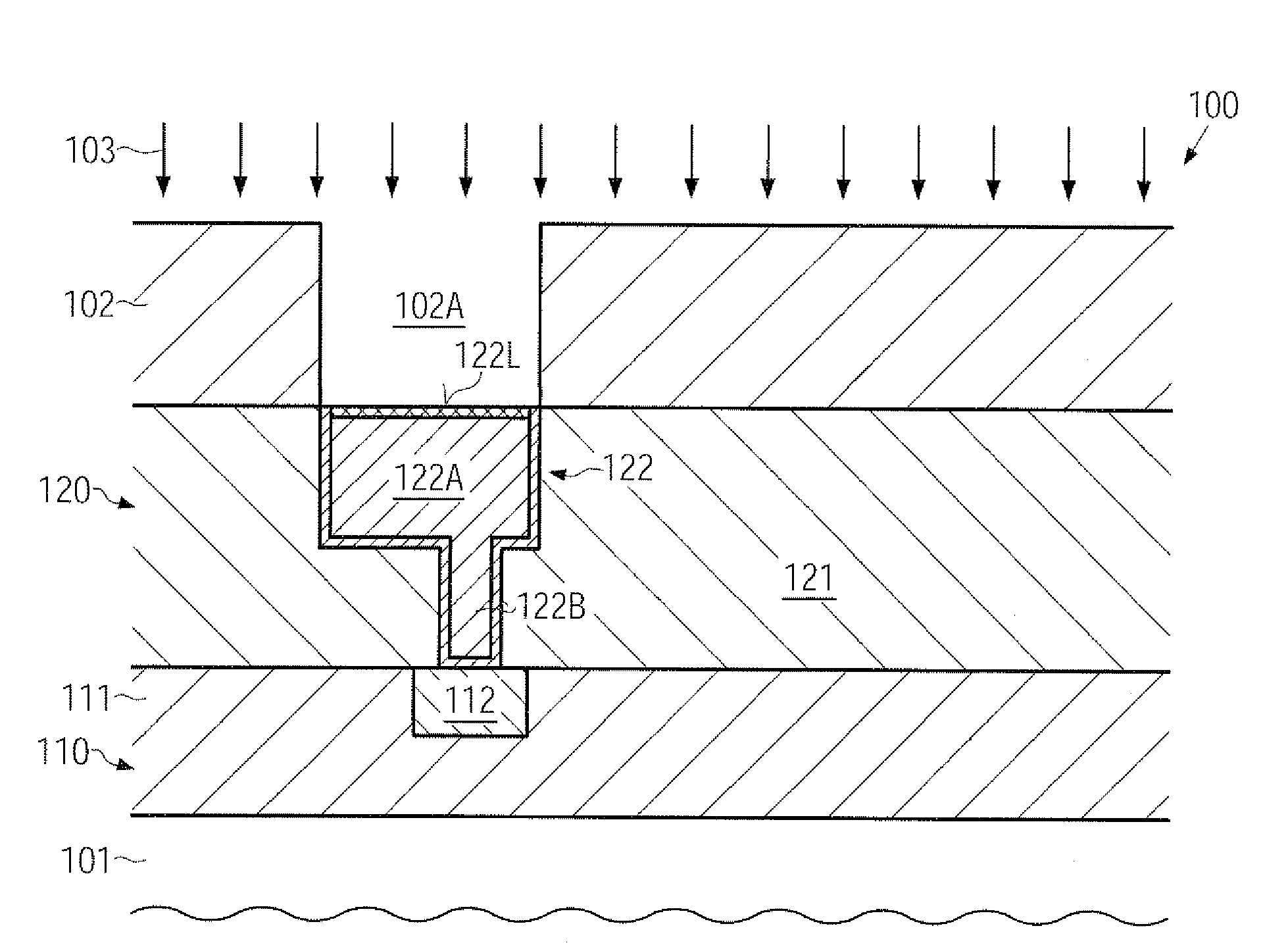
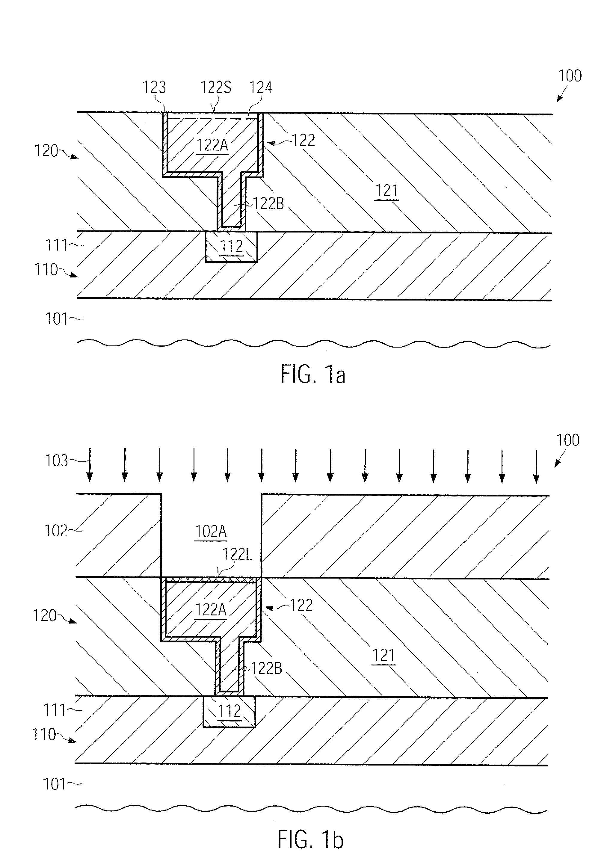
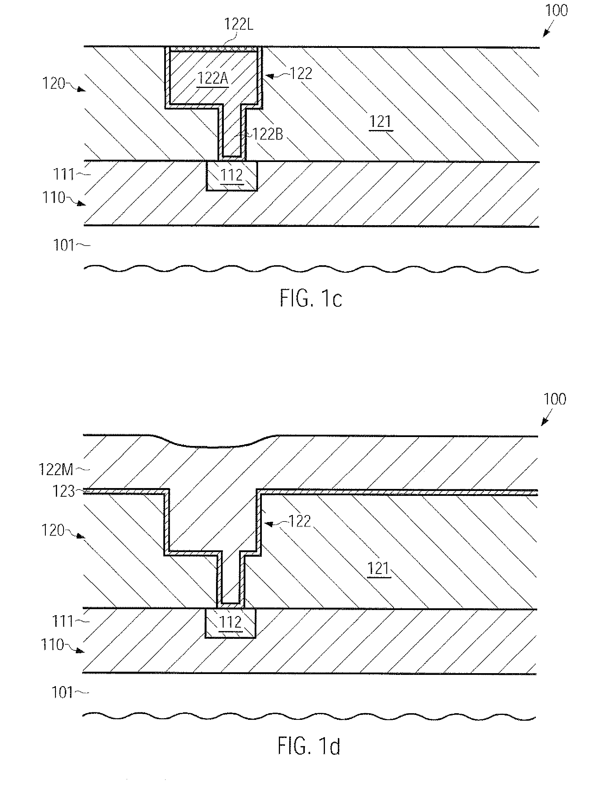
[0024]The present subject matter will now be described with reference to the attached figures. Various structures, systems and devices are schematically depicted in the drawings for purposes of explanation only and so as to not obscure the present disclosure with details that are well kno...


PUM

PropertyMeasurementUnit
widthaaaaaaaaaa
diameteraaaaaaaaaa
aspect ratioaaaaaaaaaa

Abstract

By introducing a metallic species into an exposed surface area of a copper region, the electromigration behavior of this surface area may be significantly enhanced. The incorporation of the metallic species may be accomplished in a highly selective manner so as to not unduly affect dielectric material positioned adjacent to the metal region, thereby essentially avoiding undue increase of leakage currents.

Description

BACKGROUND OF THE INVENTION[0001]1. FIELD OF THE INVENTION[0002]Generally, the present disclosure relates to the formation of microstructures, such as advanced integrated circuits, and, more particularly, to the formation of conductive structures, such as copper-based metallization layers, and techniques to reduce electromigration and other stress-induced mass transport effects during operation.[0003]2. DESCRIPTION OF THE RELATED ART[0004]In the field of fabricating modern microstructures, such as integrated circuits, there is a continuous drive to steadily reduce the feature sizes of microstructure elements, thereby enhancing the functionality of these structures. For instance, in modern integrated circuits, minimum feature sizes, such as the channel length of field effect transistors, have reached the deep sub-micron range, thereby increasing performance of these circuits in terms of speed and / or power consumption. As the size of individual circuit elements is reduced with every n...

Claims


Application Information

Patent Timeline
Patent Type & Authority Applications(United States)
IPC IPC(8): H01L21/44
CPCH01L21/76849H01L21/76883H01L21/76858
Inventor LEHR, MATTHIASMEYER, MORITZ-ANDREASLANGER, ECKHARD
Owner GLOBALFOUNDRIES INC
Why Eureka
Try Eureka