Solar Thermal Power System

a solar thermal and power system technology, applied in the direction of steam generation using solar heat, steam separation arrangement, lighting and heating apparatus, etc., can solve the problems of difficult control of once-through mode, requiring a more complex control system, and difficulty in controlling dsg systems, etc., to achieve simple efficient

Inactive Publication Date: 2009-08-13
LAWRENCE LIVERMORE NAT SECURITY LLC
View PDF14 Cites 75 Cited by
  • Summary
  • Abstract
  • Description
  • Claims
  • Application Information

AI Technical Summary

Benefits of technology

[0012]The present invention is generally directed to a solar thermal power generation system capable of providing a simple efficient solution to the problems of solar field control under solar radiation transients and the related problem of the instability of two-phase flow inside the receiver tubes, and which provides a suitable thermal energy storage technology for DSG processes and systems. In particular, th

Problems solved by technology

On the other hand, the once-through mode is not easy to control, requiring a more complex control system.” Indeed, these authors needed to implement a set of four control loops for the once-through mode.
The difficulty of controlling DSG systems stems from the combined effects of predictable variations in solar illumination through the diurnal cycle, the unpredictable variations produced by transients from passing clouds or other obscurations, and the effects of the fundamental two-phase fluid flow Ledinegg instability.
As is known in the art, as heat is applied to a conventional boiler tube, there is a tendency for the boiling water to “chug and spit” in an irregular and unstable fashion as it boils.
This fluid flow instability causes the familiar gurgling and sputtering noises often heard in coffee percolators.
The combination of fluid flow instability and solar transients tends to have as a consequence

Method used


Image

  • Solar Thermal Power System
  • Solar Thermal Power System
  • Solar Thermal Power System

Examples


Embodiment Construction

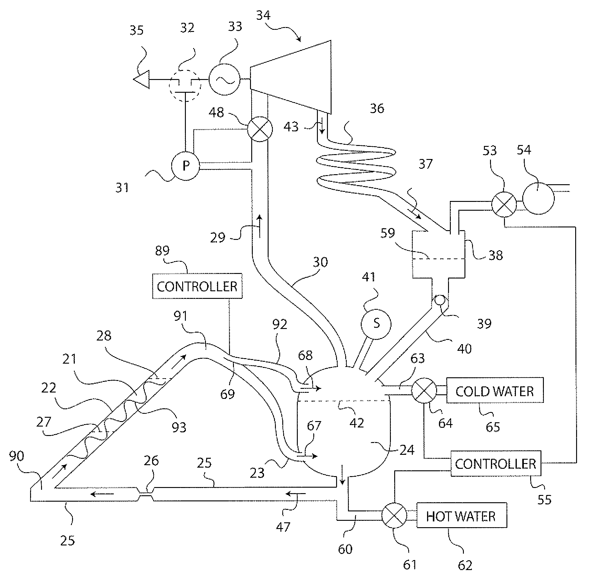
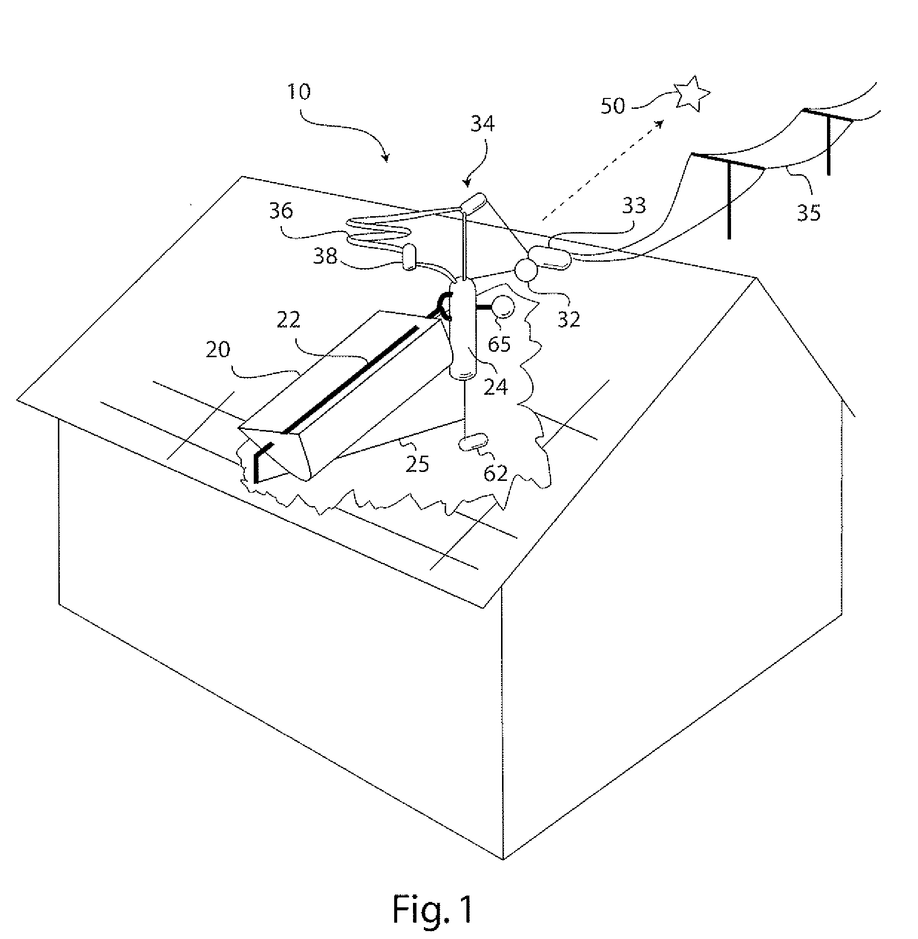
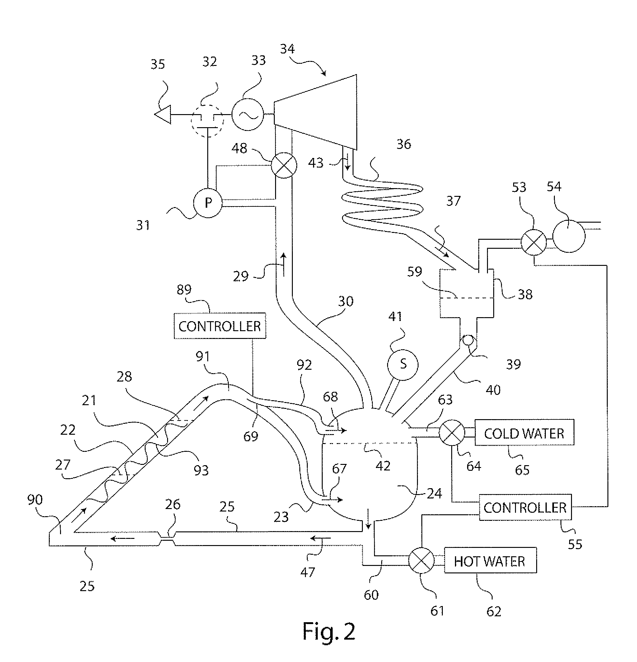
[0021]A first example embodiment of the solar thermal power system of the present invention is illustrated in FIGS. 1 and 2, and generally indicated at reference character 10. In particular, FIG. 2 shows a schematic view of an arrangement / configuration of the main components of the system 10, and FIG. 1 shows an illustrative installation of the system on a building structure, such as a residential dwelling. As can be best seen in FIG. 2, the main components of the present invention include a pressure vessel 24, a boiler tube 22, a solar concentrator (20 in FIG. 1), an expander 34, a condenser 36, and a reservoir 38, whose functions and system operations are described next in greater detail.

[0022]As shown in FIG. 2, the boiler tube 22 has an inlet end 90 fluidically connected to the pressure vessel (preferably at the bottom of the pressure vessel) via fluid line, duct, or conduit 25, and an outlet end 91 fluidically connected at a different location of the pressure vessel 24 (e.g. at...


PUM


Abstract

A solar thermal power generator includes an inclined elongated boiler tube positioned in the focus of a solar concentrator for generating steam from water. The boiler tube is connected at one end to receive water from a pressure vessel as well as connected at an opposite end to return steam back to the vessel in a fluidic circuit arrangement that stores energy in the form of heated water in the pressure vessel. An expander, condenser, and reservoir are also connected in series to respectively produce work using the steam passed either directly (above a water line in the vessel) or indirectly (below a water line in the vessel) through the pressure vessel, condense the expanded steam, and collect the condensed water. The reservoir also supplies the collected water back to the pressure vessel at the end of a diurnal cycle when the vessel is sufficiently depressurized, so that the system is reset to repeat the cycle the following day. The circuital arrangement of the boiler tube and the pressure vessel operates to dampen flow instabilities in the boiler tube, damp out the effects of solar transients, and provide thermal energy storage which enables time shifting of power generation to better align with the higher demand for energy during peak energy usage periods.

Description

I. FEDERALLY SPONSORED RESEARCH OR DEVELOPMENT[0001]The United States Government has rights in this invention pursuant to Contract No. W-7405-ENG-48 between the United States Department of Energy and the University of California for the operation of Lawrence Livermore National Laboratory.II. FIELD OF THE INVENTION[0002]This invention relates to power generation systems. In particular, the invention relates to a solar thermal power plant using solar heat energy in a direct steam generation (DSG) process, wherein a liquid phase of a phase changing fluid (e.g. water) is provided by a pressure vessel to a boiler tube where concentrated solar radiation heating takes place, and a gaseous phase of a phase changing fluid (e.g. steam) is cycled back to the pressure vessel, so as to enable flow control under rapidly varying solar heating transients and two-phase working fluid instability conditions, and to enable heat energy storage in the pressure vessel for later use in the production of el...

Claims


Application Information

Patent Timeline
IPC IPC(8): F03G6/06
CPCF01K3/008F01K3/12Y02E10/46F03G6/065F22B1/006F01K3/16Y02T10/7072
Inventor BENNETT, CHARLES L.
Owner LAWRENCE LIVERMORE NAT SECURITY LLC
Why Eureka
Try Eureka