System, method and apparatus for creating an electrical glow discharge

a technology of electrical glow discharge and apparatus, which is applied in the direction of plasma technique, insulation, and well accessories, etc., can solve the problems of water production, well may have to be shut, and reduce production, so as to prevent electrical arcing, prevent electrical arcing, and prevent electrical arcing

Active Publication Date: 2009-08-13
FORET PLASMA LABS
View PDF98 Cites 42 Cited by
  • Summary
  • Abstract
  • Description
  • Claims
  • Application Information

AI Technical Summary

Benefits of technology

[0015]More specifically, the present invention provides an apparatus for creating an electric glow discharge that includes a first electrically conductive screen, a second electrically conductive screen, one or more insulators attached to the first electrically conductive screen and the second electrically conductive screen, a non-conductive granular material disposed within the gap, a first electrical terminal electrically connected to the first electrically conductive screen, and a second electrical terminal electrically connected to the second electrically conductive screen. The insulator(s) maintain a substantially equidistant gap between the first electrically conductive screen and the second electrically conductive screen. The non-conductive granular material (a) does not pass through either electrically conductive screen, (b) allows an electrically conductive fluid to flow between the first electrically conductive screen and the second electrically conductive screen, and (c) prevents electrical arcing between the electrically conductive screens during the electric glow discharge. The electric glow discharge is created whenever: (a) the first electrical terminal is connected to an electrical power source such that the first electrically conductive screen is a cathode, the second electrical terminal is connected to the electrical power supply such that the second electrically conductive screen is an anode, and the electrically conductive fluid is introduced into the gap, or (b) the first electrical terminal and the second electrical terminal are both connected to the electrical power supply such that both electrically conductive screens are the cathode, and the electrically conductive fluid is introduced between both electrically conductive screens and an external anode connected to the electrical power supply.
[0016]In addition, the present invention provides a method for creating an electric glow discharge by providing an electric glow apparatus, introducing an electrically conductive fluid into the gap, and connecting the electrical terminals to an electrical power supply such that the first electrically conductive screen is a cathode and the second electrically conductive screen is an anode. The electric glow discharge apparatus includes a first electrically conductive screen, a second electrically conductive screen, one or more insulators attached to the first electrically conductive screen and the second electrically conductive screen, a non-conductive granular material disposed within the gap, a first electrical terminal electrically connected to the first electrically conductive screen, and a second electrical terminal electrically connected to the second electrically conductive screen. The insulator(s) maintain a substantially equidistant gap between the first electrically conductive screen and the second electrically conductive screen. The non-conductive granular material (a) does not pass through either electrically conductive screen, (b) allows an electrically conductive fluid to flow between the first electrically conductive screen and the second electrically conductive screen, and (c) prevents electrical arcing between the electrically conductive screens during the electric glow discharge. The electric glow discharge is created whenever: (a) the first electrical terminal is connected to an electrical power source such that the first electrically conductive screen is a cathode, the second electrical terminal is connected to the electrical power supply such that the second electrically conductive screen is an anode, and the electrically conductive fluid is introduced into the gap, or (b) the first electrical terminal and the second electrical terminal are both connected to the electrical power supply such that both electrically conductive screens are the cathode, and the electrically conductive fluid is introduced between both electrically conductive screens and an external anode connected to the electrical power supply.
[0017]Moreover, the presen...

Problems solved by technology

There are many problems associated with the production of oil and gas resources.
Likewise, even during peak production of a well, a well may have to be shut in due to paraffin plugging the production tubing.
This can cause several problems ranging from reduced production to parting or breaking of the sucker rod connected to the surface pump jack.
Another problem associated with most oil and gas wells is produced water.
However, emerging issues with respect to the renewed interest in oil shale development range from water resources, to green house gas emissions to basic infrastructure needs.
Likewise, the Canadian oil sands has its own problems ranging from very large tailings ponds to a lack of upgrading capacity for the bitumen recovered from the oil sands.
In addition, the steam assisted gravity drainage (SAGD) process utilizes copious amounts of energy to produce steam.
Two problems associated wit...

Method used


Image

  • System, method and apparatus for creating an electrical glow discharge
  • System, method and apparatus for creating an electrical glow discharge
  • System, method and apparatus for creating an electrical glow discharge

Examples


Embodiment Construction

[0033]While the making and using of various embodiments of the present invention are discussed in detail below, it should be appreciated that the present invention provides many applicable inventive concepts that can be embodied in a wide variety of specific contexts. The specific embodiments discussed herein are merely illustrative of specific ways to make and use the invention and do not delimit the scope of the invention.

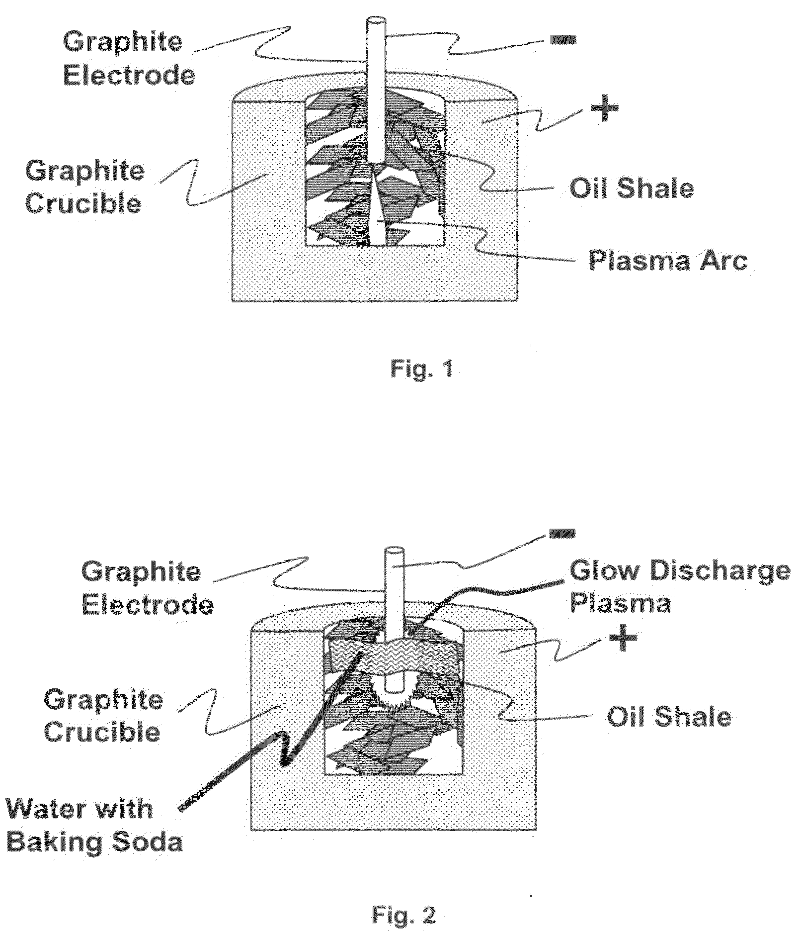
[0034]It will be understood that the terms plasma electrolysis, glow discharge, glow discharge plasma and electrochemical plasma will be used interchangeably throughout this disclosure. Likewise, it will be understood that plasma electrolysis is substantially different and clearly differentiated within the art from traditional electrolysis or simple electrochemical reactions commonly referred to as REDOX (reduction oxidation) reactions. In plasma electrolysis a “plasma” is formed and maintained around the cathode which is surrounded by an electrolyte thus allowin...


PUM


Abstract

The present invention provides system, method and apparatus for creating an electric glow discharge that includes a first and second electrically conductive screens having substantially equidistant a gap between them, one or more insulators attached to the electrically conductive screens, and a non-conductive granular material disposed within the gap. The electric glow discharge is created whenever: (a) the first electrically conductive screen is connected to an electrical power source such that it is a cathode, the second electrically conductive screen is connected to the electrical power supply such that it is an anode, and the electrically conductive fluid is introduced into the gap, or (b) both electrically conductive screens are connected to the electrical power supply such they are the cathode, and the electrically conductive fluid is introduced between both electrically conductive screens and an external anode connected to the electrical power supply.

Description

PRIORITY CLAIM AND CROSS-REFERENCE TO RELATED APPLICATIONS[0001]This patent application is non-provisional patent application of U.S. provisional patent application 60 / 980,443 filed on Oct. 16, 2007 and entitled “System, Method and Apparatus for Carbonizing Oil Shale with Electrolysis Plasma Well Screen” and U.S. provisional patent application 61 / 028,386 filed on Feb. 13, 2008 and entitled “High Temperature Plasma Electrolysis Reactor Configured as an Evaporator, Filter, Heater or Torch.” All of the foregoing applications are hereby incorporated by reference in their entirety.FIELD OF THE INVENTION[0002]The present invention relates to the field of processing oil shale and more specifically to carbonizing oil shale with electrochemical plasma. The present invention can be applied to both surface methods and equipment as well as applied within an oil shale formation for in situ plasma electrolysis. The present invention also includes a novel plasma electrolysis well screen. In additi...

Claims


Application Information

Patent Timeline
IPC IPC(8): E21B36/00E21B43/24H05B31/26C25B9/19
CPCE21B36/04E21B43/082E21B43/17E21B36/008E21B43/243E21B43/2401C25B1/00C25B11/03C25B13/02C25B13/08C25B9/65C25B9/19H05H1/48H05H1/471E21B43/08C10B23/00C10B53/06E21B43/2405
Inventor FORET, TODD
Owner FORET PLASMA LABS
Why Eureka
Try Eureka