Mems transducer and manufacturing method therefor

a technology of micro-electromagnetic system and transducer, which is applied in the direction of fluid pressure measurement, fluid pressure measurement by electric/magnetic elements, instruments, etc., can solve the problems of affecting the mechanical function of mems transducers, affecting the mechanical structure of mems transducers, and causing distortions in mems transducers

Inactive Publication Date: 2009-08-13
YAMAHA CORP
View PDF4 Cites 41 Cited by
  • Summary
  • Abstract
  • Description
  • Claims
  • Application Information

AI Technical Summary

Benefits of technology

[0013]It is an object of the present invention to provide an MEMS transducer which i

Problems solved by technology

When nitride materials and nitrogen oxide materials are used for protective films, distortions may occur in

Method used


Image

  • Mems transducer and manufacturing method therefor
  • Mems transducer and manufacturing method therefor
  • Mems transducer and manufacturing method therefor

Examples


first embodiment

1. First Embodiment

[0079](1) Constitution

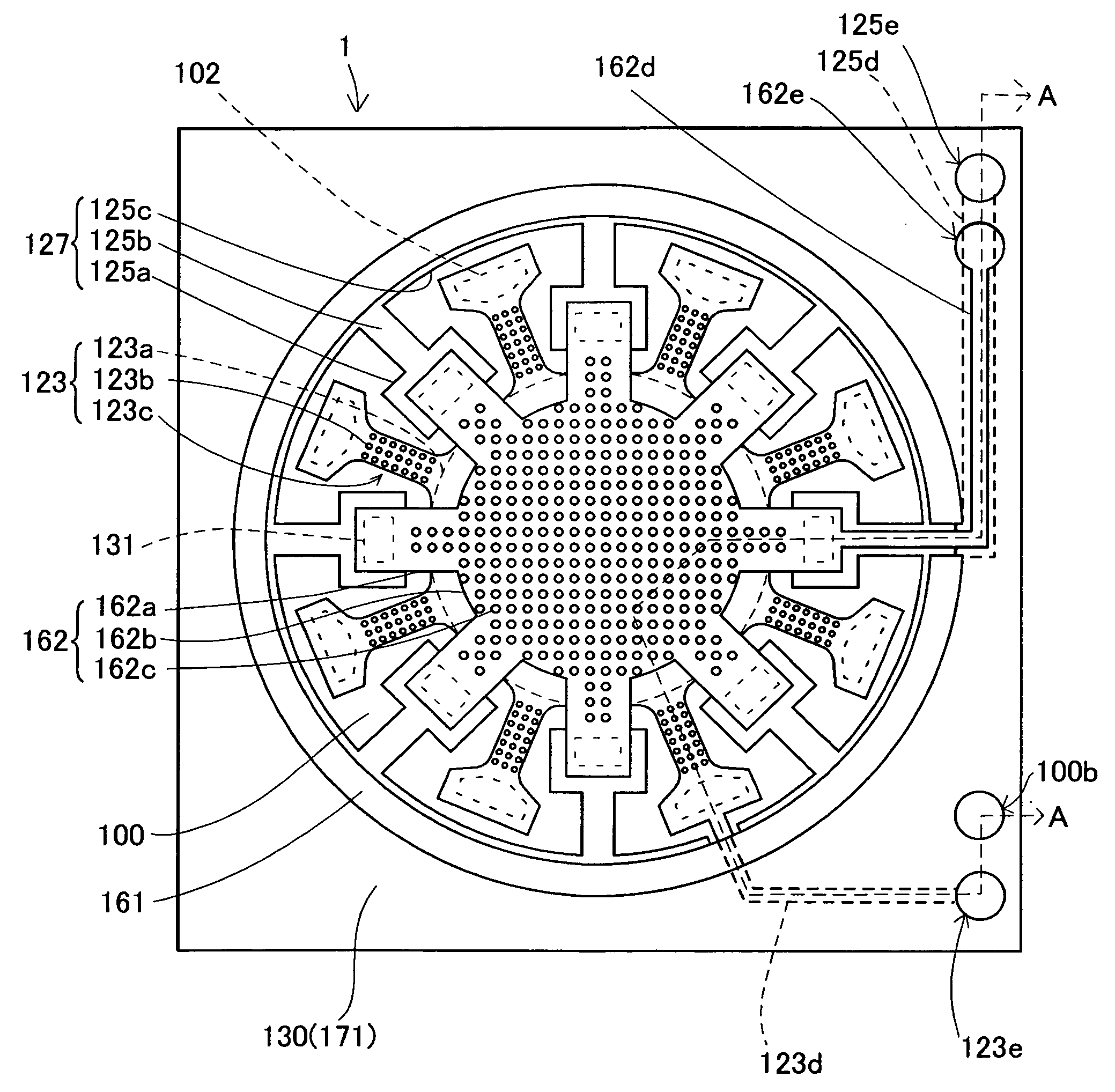
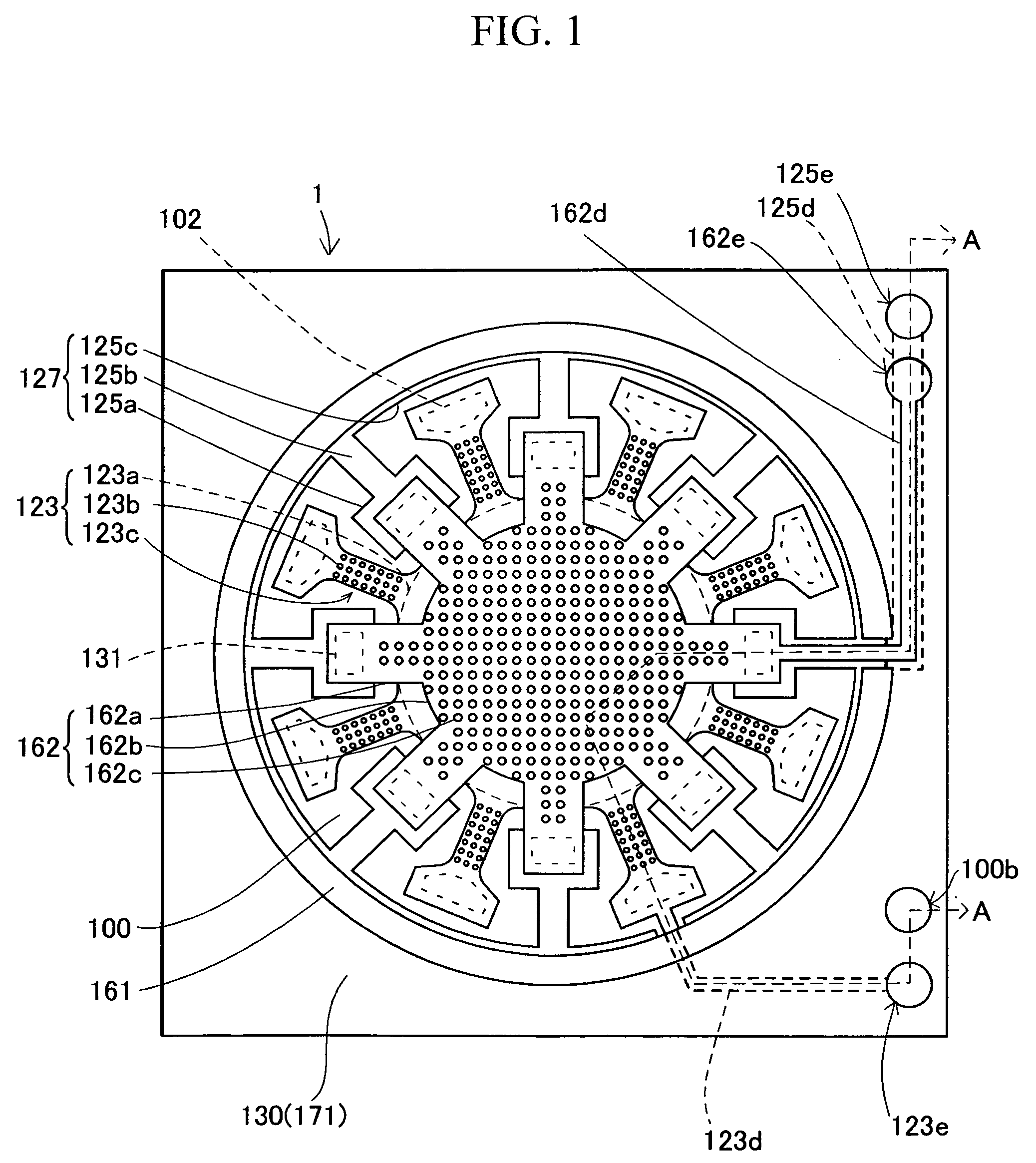
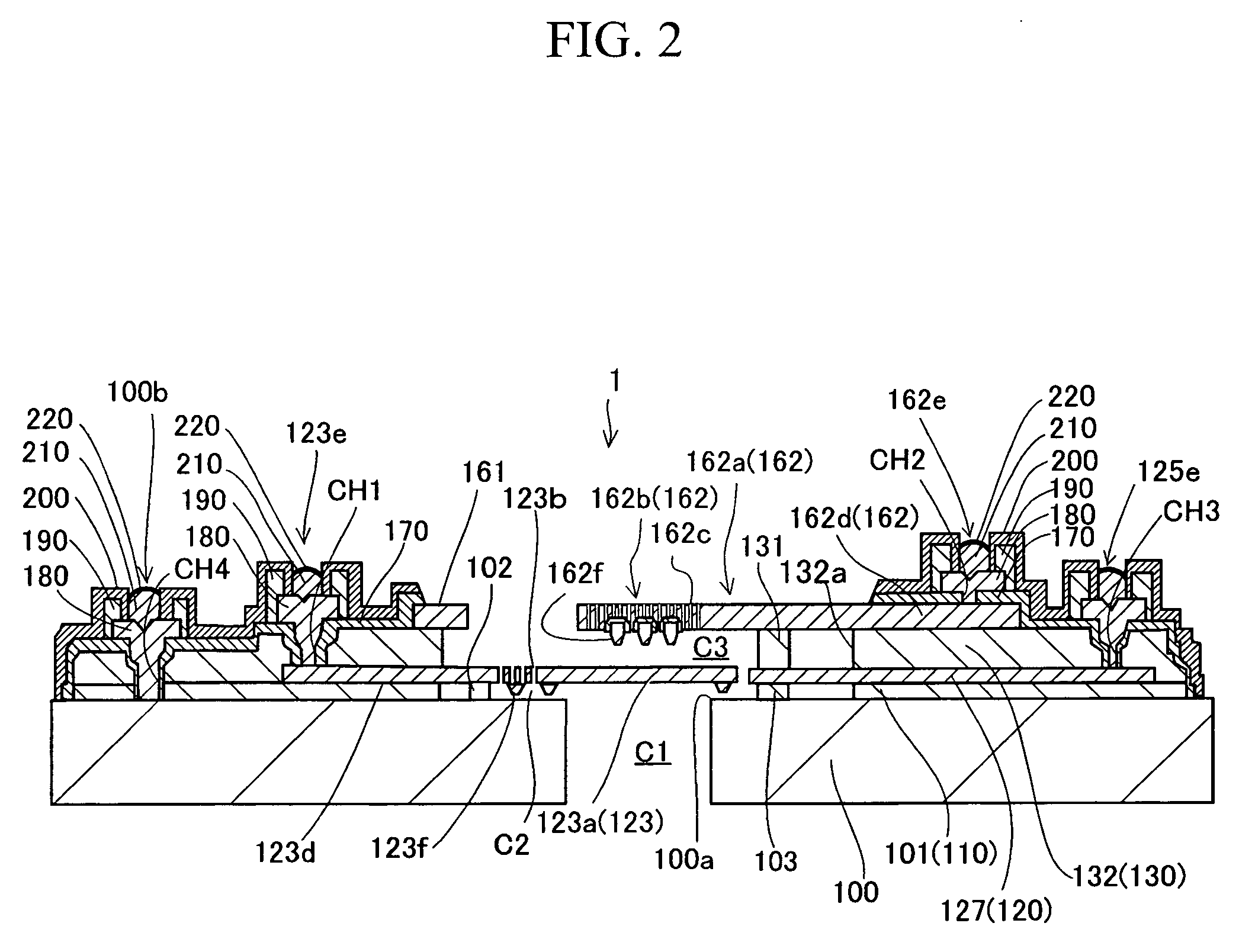
[0080]FIG. 1 shows a sensor die 1 of a condenser microphone (i.e. an example of an MEMS transducer) in accordance with a first embodiment of the preset invention. FIG. 2 is a sectional view take along line A-A in FIG. 1 with respect to the sensor die 1; and FIG. 3 shows the film-laminating structure of the sensor die 1. For the sake of simplification of illustrations, FIGS. 1 and 3 omit higher layers (which are shown in FIG. 2) formed above an upper conductive layer. The condenser microphone is constituted of the sensor die 1, a circuit die (including a voltage supply and an amplifier, not shown), and a package (not shown) for enclosing them.

[0081]The sensor die 1 is a movable component having a film-laminating structure including a substrate 100, a lower insulating film 110, a lower conductive film 120, an upper insulating film 130, an upper conductive film 160, a surface insulating film 170, pad conductive films 180, bump films 210, bump pr...

second embodiment

2. Second Embodiment

[0131]A sensor chip 10 of a condenser microphone according to a second embodiment of the present invention will be described with reference to FIGS. 26 to 28, FIGS. 29A and 29B, and FIGS. 30 to 48, wherein parts identical to those of the sensor die 1 of the condenser microphone shown in FIGS. 1 to 3, FIGS. 4A to 4D, FIGS. 5 to 12, FIGS. 13A and 13B, and FIGS. 14 to 25 are designated by the same reference numerals; hence, duplicate descriptions thereof are simplified as necessary.

[0132](1) Constitution

[0133]FIG. 26 shows the constitution of the sensor chip 10, which is an MEMS structure of the condenser microphone according to the second embodiment of the present invention; FIG. 27 is a sectional view of the sensor chip 10; and FIG. 28 is an exploded perspective view showing the film-laminating structure in the sensor chip 10. The condenser microphone (serving as an MEMS transducer) is constituted of the sensor chip 10, a circuit chip (including a power circuit an...


PUM


Abstract

An MEMS transducer is constituted of a diaphragm, a plate, a support structure for supporting the diaphragm and the plate with a gap layer surrounded by an interior wall, an electrode film (e.g. a pad conductive film) for covering a contact hole formed in the support structure, and a protective film (e.g. a pad protective film) which is formed on the support structure externally of the interior wall so as to cover the side surface of the electrode film having low chemical stability. The protective film is formed in the limited area including a part of the surface of the electrode film except for its center portion and the surrounding area of the electrode film. This allows the protective film to use materials having high membrane stress such as silicon nitride or silicon nitride oxide.

Description

BACKGROUND OF THE INVENTION[0001]1. Field of the Invention[0002]The present invention relates to MEMS (Micro Electro Mechanical System) transducers applied to MEMS sensors used in miniature condenser microphones, vibration sensors, pressure sensors, and acceleration sensors, for example.[0003]The present invention also relates to manufacturing methods of MEMS transducers.[0004]The present application claims priority on Japanese Patent Application No. 2007-341440, and Japanese Patent Application No. 2007-341426, the contents of which are incorporated herein by reference.[0005]2. Description of the Related Art[0006]Various types of miniature condenser microphones, which are manufactured by use of manufacturing processes of semiconductor devices, have been developed and disclosed in various documents such as Patent Documents 1, 2, 3, and Non-Patent Document 1.[0007]Patent Document 1: Japanese Patent Application Publication No. H09-50877[0008]Patent Document 2: Japanese Patent Applicati...

Claims


Application Information

Patent Timeline
IPC IPC(8): H01L29/84H01L21/50
CPCB81B3/0021B81B2201/0257H01L29/84B81B2203/04B81B2203/0127
Inventor OMURA, MASAYOSHISUZUKI, TAMITOSUZUKI, YUKITOSHI
Owner YAMAHA CORP
Why Eureka
Try Eureka