
Plasma processing apparatus and method, and storage medium

a processing apparatus and a technology for plasma, applied in the direction of electric discharge tubes, decorative arts, instruments, etc., can solve the problems of non-uniform density of plasma, decrease of control range of etching rate or the like, non-uniform processing or charge-up damage, etc., to reduce drawbacks such as cd non-uniformity and increase the control range of plasma processing. , the effect of increasing the uniformity of the control rang

Active Publication Date: 2009-08-20
TOKYO ELECTRON LTD
View PDF2 Cites 10 Cited by
  • Summary
  • Abstract
  • Description
  • Claims
  • Application Information

AI Technical Summary

Benefits of technology

[0012]In view of the above, the present invention provides a plasma processing apparatus and a plasma processing method capable of suppressing drawbacks such as CD non-uniformity and the like caused by deposits and increasing a control range of uniformity of plasma processing in a lower electrode dual frequency application type.
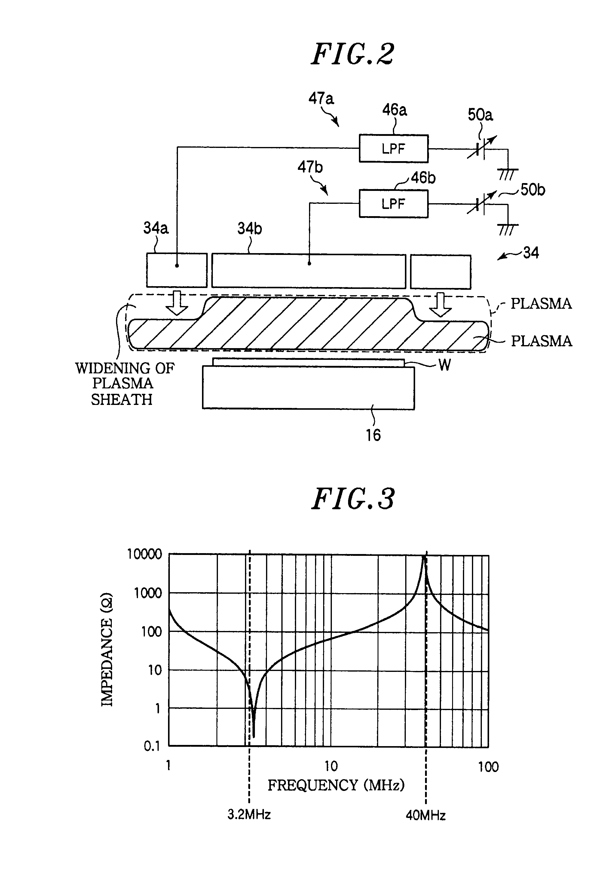
[0025]Hence, the first high frequency power of the first high frequency power is guided to the outer electrode. Further, a higher plasma density can be obtained, and the control margin of the plasma density in the outer portion can be increased. Moreover, the high frequency power of the second high frequency power is isolated from the outer electrode, and the self-bias effect obtained by applying the first high frequency power is suppressed. Furthermore, the deposition enhancement effect of the plasma by the DC voltage application can be reduced, so that it is possible to suppress the drawback such as CD non-uniformity or the like caused by deposits.

Problems solved by technology

Since a plasma potential at the central portion becomes higher than that at the edge portion, the plasma density becomes non-uniform.
Moreover, in the low-pressure and low-ion energy plasma generated by using the high frequency power of the high frequency, the non-uniformity of the plasma density caused by the in-plane non-uniformity of the plasma potential easily leads to non-uniformity of the processing or charge-up damages.
However, even when the technique disclosed in Japanese Patent Laid-open Application No. 2006-286814 is applied to the plasma processing apparatus of the lower electrode dual frequency application type, there are generated problems in which a control range of an etching rate or the like decreases and deposits increased due to an improved etching rate causes CD (Critical Dimension) non-uniformity.

Method used


Image

  • Plasma processing apparatus and method, and storage medium
  • Plasma processing apparatus and method, and storage medium
  • Plasma processing apparatus and method, and storage medium

Examples


Embodiment Construction

[0034]Embodiments of the present invention will be described with reference to the accompanying drawings which form a part hereof.

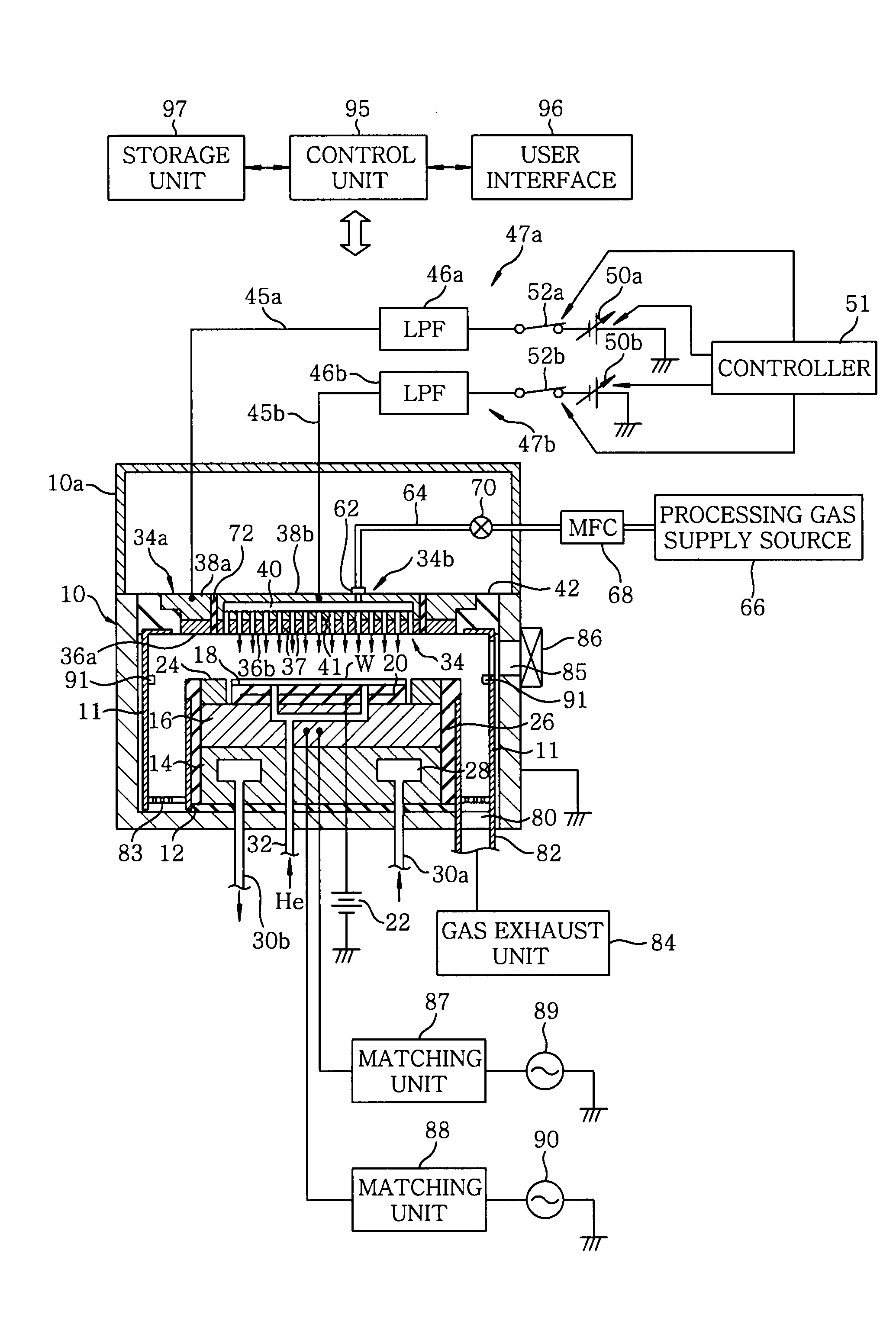
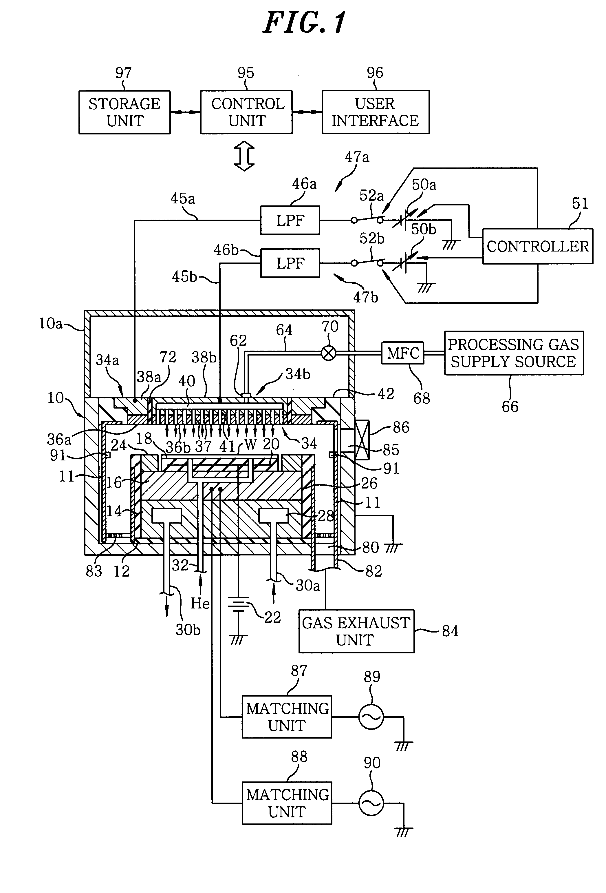
[0035]Hereinafter, a plasma etching apparatus in accordance with an embodiment of a plasma processing apparatus of the present invention will be described. FIG. 1 is a schematic cross sectional view showing a plasma etching apparatus in accordance with an embodiment of the present invention. This plasma etching apparatus is configured as a capacitively coupled parallel plate type plasma etching apparatus having a substantially cylindrical chamber (processing vessel) 10 made of, e.g., aluminum having an anodically oxidized surface. The chamber 10 is frame-grounded.

[0036]A columnar susceptor support 14 is provided on a bottom portion of the chamber 10 via an insulating plate 12 made of ceramic or the like. Further, a susceptor 16 made of, e.g., aluminum, is disposed on the susceptor support 14. The susceptor 16 serves as a lower electrode, and mounts thereo...


PUM

PropertyMeasurementUnit
Frequencyaaaaaaaaaa
Frequencyaaaaaaaaaa
Frequencyaaaaaaaaaa

Abstract

A plasma processing apparatus includes a vacuum evacuable processing chamber, a first electrode divided into an outer electrode and an inner electrode, a second electrode, a first and a second high frequency power application unit for applying to the second electrode a first and a second high frequency power having a relatively high frequency and a relatively low frequency, respectively, a first and a second DC voltage application circuit apply a DC voltage to the outer and the inner electrode, respectively, and a processing gas supply unit. A space between the first electrode and the second electrode serves as a plasma generation space, and frequency-impedance characteristics of the outer electrode are set such that the impedance increases at the frequency of the second high frequency power and decreases at the frequency of the first high frequency power as the DC voltage applied to the outer electrode increases.

Description

FIELD OF THE INVENTION [0001]The present invention relates to a plasma processing apparatus and method for performing plasma processing on a substrate to be processed such as a semiconductor substrate or the like, and a storage medium.BACKGROUND OF THE INVENTION [0002]For example, in a manufacturing process of semiconductor devices, a single wafer plasma etching process for etching a substrate to be processed by using a plasma while using a resist as a mask is widely employed to form a predetermined pattern on a predetermined layer on a semiconductor wafer as the substrate to be processed.[0003]Among various plasma processing apparatuses for performing such single wafer plasma etching process, a capacitively coupled parallel plate type etching apparatus has been mainly used.[0004]The capacitively coupled parallel plate type plasma etching apparatus includes a pair of parallel plate type electrodes (an upper electrode and a lower electrode) disposed in a chamber, wherein a substrate ...

Claims


Application Information

Patent Timeline
IPC IPC(8): H01L21/306
CPCH01J37/32027H01J37/32165H01J37/32091H01L21/3065
Inventor IWATA, MANABUNAKAYAMA, HIROYUKIMASUZAWA, KENJIHONDA, MASANOBU
Owner TOKYO ELECTRON LTD
Learn More