
Laser heated discharge plasma EUV source

a plasma euv source and laser irradiation technology, applied in the direction of optical radiation measurement, instruments, therapy, etc., can solve the problems of low conversion efficiency of laser light into euv radiation, low total lithium inventory in this approach, and high absorption of euv light by direct laser irradiation of solid density lithium targets, etc., to achieve high repetition rate and high impedance

Inactive Publication Date: 2009-08-27
PUREX
View PDF10 Cites 23 Cited by
  • Summary
  • Abstract
  • Description
  • Claims
  • Application Information

AI Technical Summary

Benefits of technology

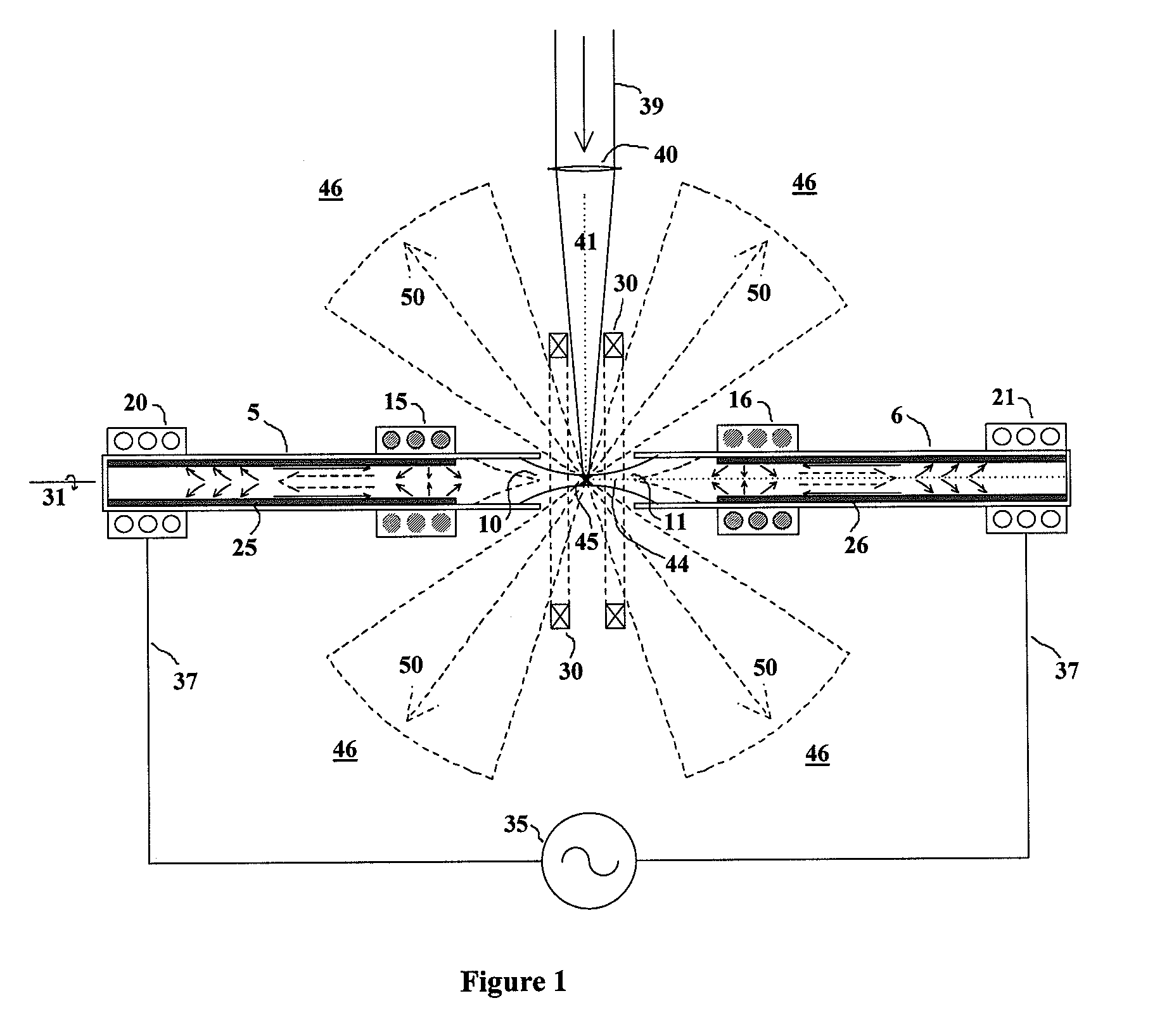
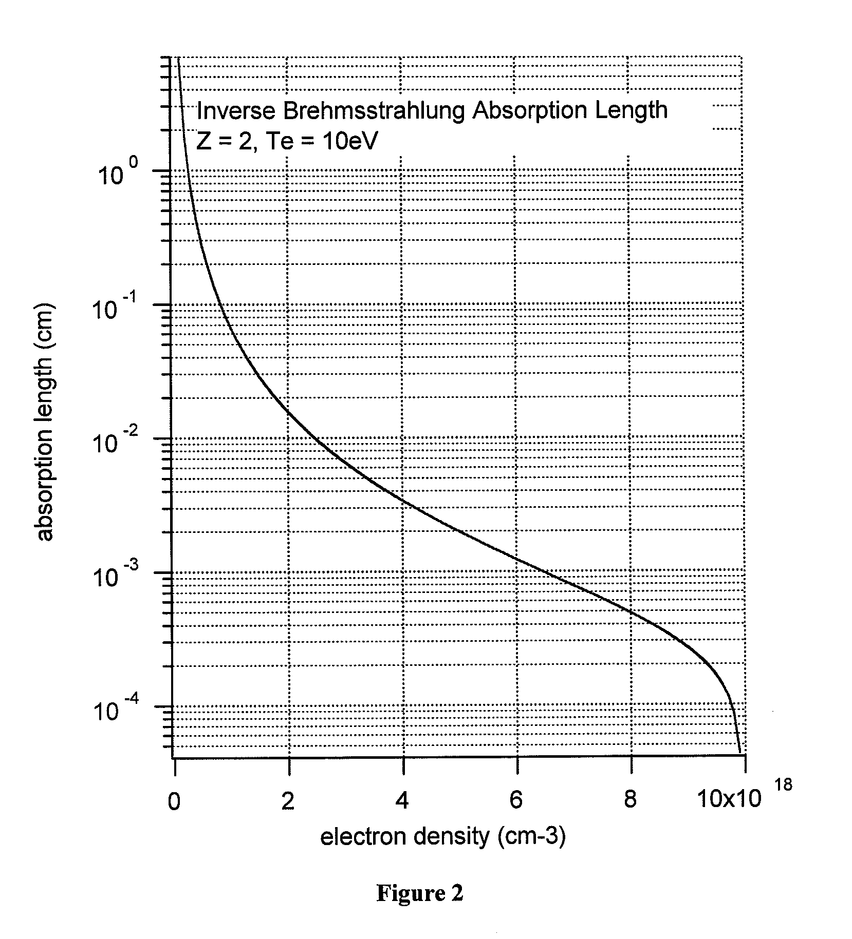
[0014]According to a second aspect of the invention, an extreme ultraviolet light source at 13.5 nanometers is based on the emission of lithium ions in which a magnetically self-confined lithium plasma of electron density less than 1019 cm−3 is produced via a pulsed discharge and the plasma energy in a small region of the plasma is increased by absorption of laser light at the wavelength of 10.6 microns, resulting in locally increased excitation of hydrogen-like lithium to its resonance level and increased radiation at 13.5 nanometers.

Problems solved by technology

In fact, the total lithium inventory in this approach can be extremely small.
Direct laser irradiation of a solid density lithium target gives low conversion efficiency from laser light into EUV radiation because there is only a very thin layer of the laser-produced plasma that is at the correct density and temperature for efficient EUV emission.
A principal problem of EUV source design stems from the extremely high absorption experienced by EUV light when passing through any solid material.
The achievement of such a high electron density is only possible at a high gas pressure which is incompatible with the collection of EUV light, unless an additional means of compression is employed wherein an initially low pressure gas is swept up into a much smaller volume just prior to the laser excitation pulse.

Method used


Image

  • Laser heated discharge plasma EUV source
  • Laser heated discharge plasma EUV source
  • Laser heated discharge plasma EUV source

Examples


first embodiment

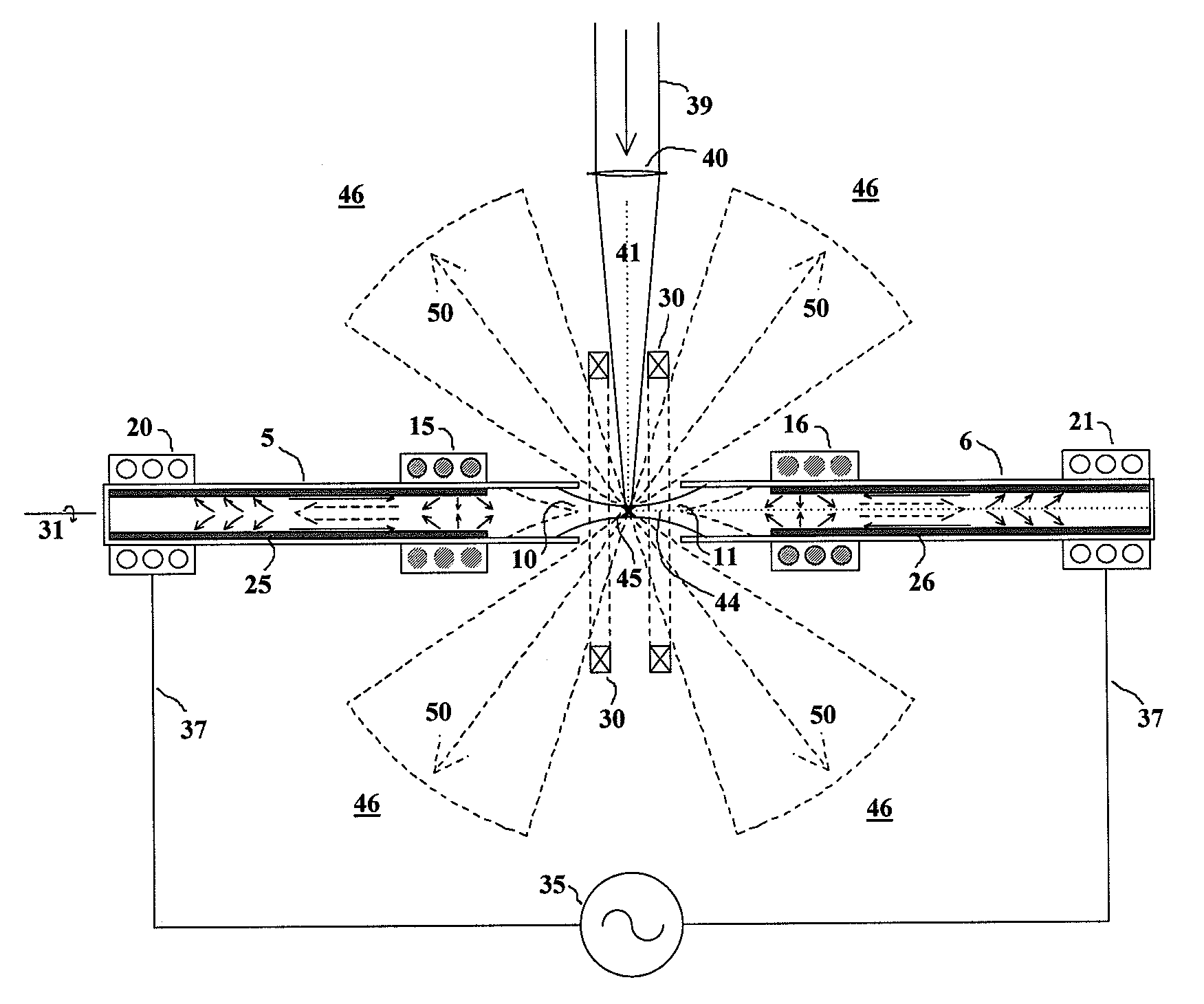
[0025]the invention is illustrated in FIG. 1, relating to linear coaxial Z-pinch confinement of the lithium plasma with heating by a transversely incident pulsed or continuous wave carbon dioxide laser. An axial magnetic field may also be applied to enhance pinch confinement stability.

second embodiment

[0026]the invention is illustrated in FIG. 4, relating to star pinch confinement of the lithium plasma with heating by a pulsed carbon dioxide laser.

third embodiment

[0027]the invention is illustrated in FIG. 7, relating to hypocycloidal pinch confinement of the lithium plasma with heating by a pulsed carbon dioxide laser.

[0028]A fourth embodiment of the invention relates to additional lithium vapor containment applied to the geometry of the first embodiment, as illustrated in FIG. 8.


PUM


Abstract

A self-magnetically confined lithium plasma which also may have an applied axial magnetic field is irradiated at sub-critical density by a carbon dioxide laser to generate extreme ultraviolet photons at the wavelength of 13.5 nm with high efficiency, high power and small source size.

Description

CROSS REFERENCE TO RELATED APPLICATION[0001]This application claims priority based on Provisional Application Ser. No. 61 / 004,656, filed Nov. 29, 2007, which is hereby incorporated by reference in its entirety.BACKGROUND OF THE INVENTION[0002]In order to have a high printing speed in extreme ultraviolet lithography, light at 13.5 nm with a minimum power of 1 kW in a narrow 2% fractional band is required out of the source into a solid angle of 2π steradians [1], with extremely low levels of contaminants and very high reliability. Two principal approaches to the production of this light have been followed to date, namely the discharge produced plasma (DPP) and the laser produced plasma (LPP). In the first of these a gaseous medium carries a pulsed high current discharge which pinches the plasma down to small dimensions with inertial and ohmic heating that induces radiation at 13.5 nm. In the second approach a pulsed laser is focused onto a solid target containing the chosen 13.5 nm ra...

Claims


Application Information

Patent Timeline
Patent Type & Authority Applications(United States)
IPC IPC(8): G01J3/10
CPCH05G2/003H05G2/005G03F7/70033
Inventor MCGEOCH, MALCOLM W.
Owner PUREX
Learn More