
Multiple ampoule delivery systems

a technology of ampoule and delivery system, which is applied in the direction of thin material processing, metallic material coating process, coating, etc., can solve the problems of destroying electronic devices, contaminating process particles, and potential loss of millions of dollars, and achieves the effect of increasing the usage of precursor chemicals, reducing the downtime of electronic devices, and high purity of precursor chemicals

Inactive Publication Date: 2009-08-27
PRAXAIR TECH INC
View PDF45 Cites 39 Cited by
  • Summary
  • Abstract
  • Description
  • Claims
  • Application Information

AI Technical Summary

Benefits of technology

This patent describes an integrated vapor phase reagent dispensing apparatus that includes multiple vessels, each containing a source chemical and a carrier gas feed inlet and outlet for dispensing the vapor phase reagent. The apparatus also includes multiple carrier gas feed / vapor phase reagent delivery manifolds that are interconnected with the vessels. The apparatus allows for the controlled delivery of vapor phase reagent to a deposition chamber. The technical effects of this invention include improved efficiency in delivering vapor phase reagent and better control over the delivery process.

Problems solved by technology

Some of the precursor chemical properties that make them challenging to handle and deliver include, for example, their exothermic reactivity with moisture and oxygen in the air.
This can lead to, in the case of a large spill, the evolution of combustible by-products and fire, and in the case of residual air in a delivery line, particulates that can contaminate the delivery lines and then be transferred to the wafer surface during process, destroying the electronic devices.
The limited thermal stability of precursor chemicals leads to, in heated ampoules, a gradual build-up of impurities in the ampoule (heel) that can reduce vapor pressure and / or contaminate the process, and decomposition in the gas lines and valves of the precursor chemical delivery manifold, resulting in particles contaminating the process.
If the ampoule should run dry in the middle of a cycle, the entire batch of wafers will be ruined resulting in a potential loss of millions of dollars.
In the case of precursor chemicals with low thermal stability and / or the property of being a solid at room temperature, the implementation of a bulk delivery system can be challenging and impractical.
For example, the challenges include having to heat and melt a large quantity of material in the reservoir and heat tracing extensive lengths of precursor chemical distribution lines to ensure the precursor chemical remains a liquid; impurity build-up in the ampoule as the impurities concentrate in the vessel from fill to fill; and thermal decomposition of the precursor chemical in idle, heated distribution lines.

Method used


Image

  • Multiple ampoule delivery systems
  • Multiple ampoule delivery systems
  • Multiple ampoule delivery systems

Examples


Embodiment Construction

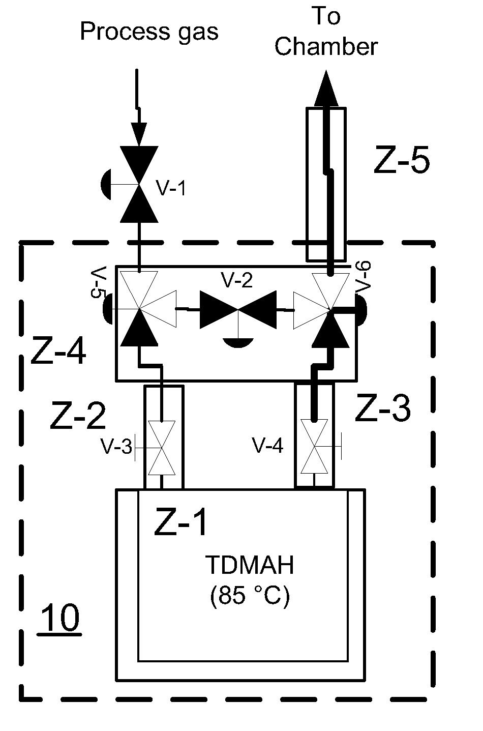
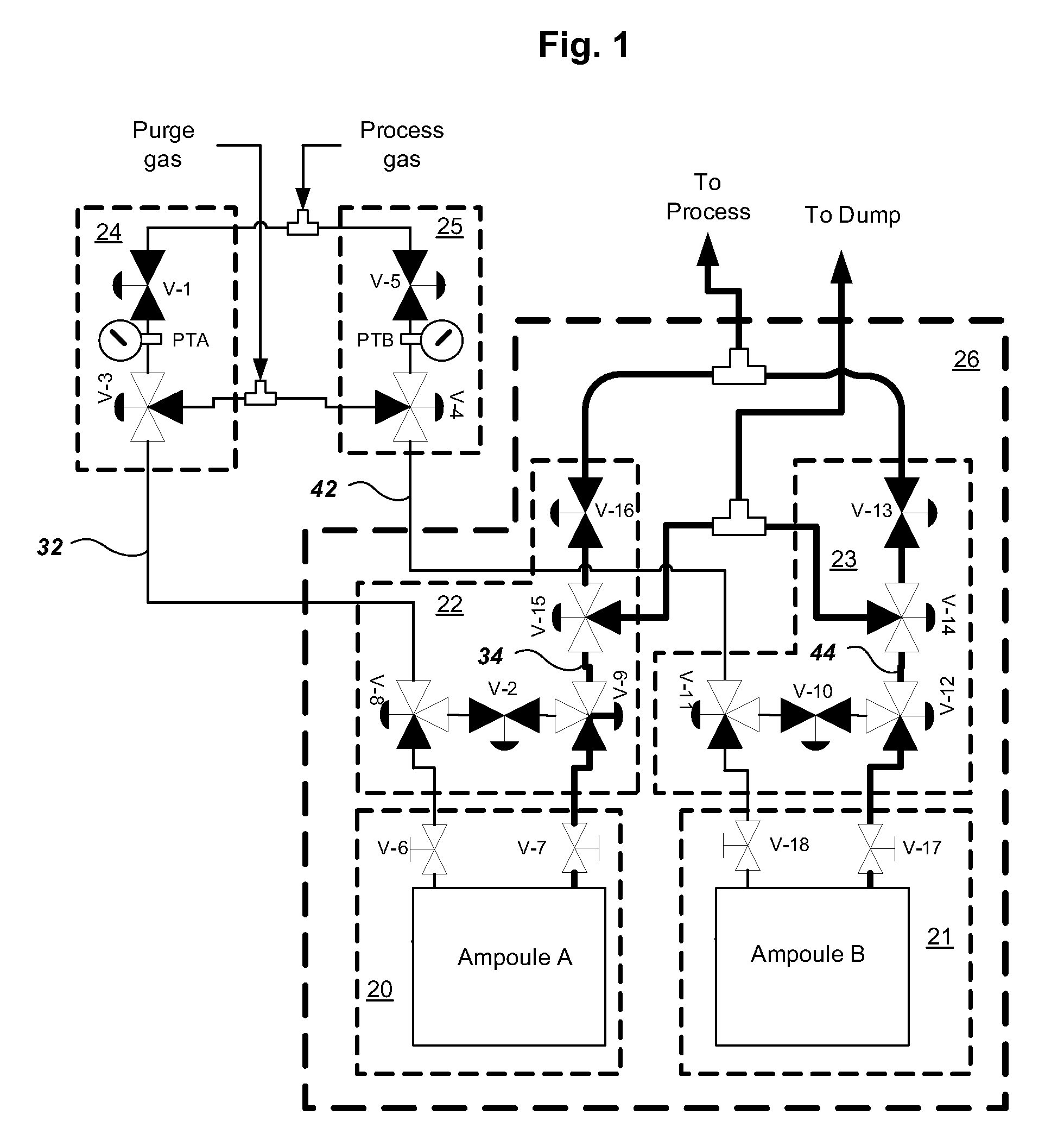
[0115]Small quantities of organometallic precursor have typically been stored in day-containers, ampoules or bubblers to be used on chemical vapor deposition or atomic layer deposition tools. As wafers have gotten larger and the usage rate of organometallic precursors has increased, the length of time a given quantity of precursor lasts has decreased. This requires more frequent ampoule changes, leading to lower tool utilization. The standard approach so far has been to 1) go to larger ampoules and 2) go to bulk refill systems where the precursor is drawn as a liquid from a large reservoir stored in the sub-fab and sent to the smaller ampoule on the tool.

[0116]This invention is unique in that, while the bulk fill solution works for certain precursors such as TMA or TMG that have been in extensive use, many newer precursors may be solids or have low thermal stability, making a bulk fill system difficult or impossible to implement for them. In an embodiment, this invention can place t...


PUM

PropertyMeasurementUnit
timeaaaaaaaaaa
temperatureaaaaaaaaaa
weightaaaaaaaaaa

Abstract

This invention relates to an integrated vapor or liquid phase reagent dispensing apparatus having a plurality of vessels and a plurality of carrier or inert gas feed / vapor or liquid phase reagent delivery manifolds, that may be used for continuously dispensing vapor or liquid phase reagents such as precursors for deposition of materials in the manufacture of semiconductor materials and devices.

Description

RELATED APPLICATIONS[0001]This invention claims priority from provisional U.S. Patent Application Ser. No. 61 / 030,578, filed Feb. 22, 2008, which is incorporated herein by reference. This application is related to U.S. patent application Ser. No. (21747-R1), filed on an even date herewith, U.S. patent application Ser. No. (21747-R2), filed on an even date herewith, and U.S. patent application Ser. No. (21747-R3), filed on an even date herewith, all of which are incorporated herein by reference.FIELD OF THE INVENTION[0002]This invention relates to an integrated vapor or liquid phase reagent dispensing apparatus having a plurality of vessels and a plurality of carrier or inert gas feed / vapor or liquid phase reagent delivery manifolds, that may be used for continuously dispensing vapor or liquid phase reagents such as precursors for deposition of materials in the manufacture of semiconductor materials and devices.BACKGROUND OF THE INVENTION[0003]High purity chemicals used in the semico...

Claims


Application Information

Patent Timeline
Patent Type & Authority Applications(United States)
IPC IPC(8): C23C16/44C23C16/54B05C11/00
CPCC23C16/45561C23C16/4481Y10T137/0324H01L21/67017
Inventor SARIGIANNIS, DEMETRIUSHOOVER, CYNTHIA A.KRAUSE, MICHAEL JOSEPHPRYOR, EDWARDCHESTERS, STEPHENSPOHN, RONALD
Owner PRAXAIR TECH INC
Learn More