

Oscillation adjusting circuit and method
a technology of oscillating adjusting circuit and circuit, which is applied in the direction of pulse automatic control, fault response, instruments, etc., can solve the problems of long locking time, easy formation of error of clock, and inconvenient transmission system of pll or dll, so as to reduce chip area, save component cost, and good selectivity
- Summary
- Abstract
- Description
- Claims
- Application Information
AI Technical Summary
Benefits of technology
Problems solved by technology
Method used
Image

Examples
first embodiment
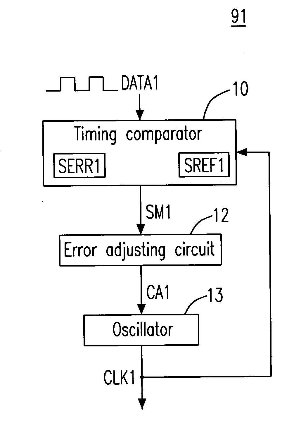
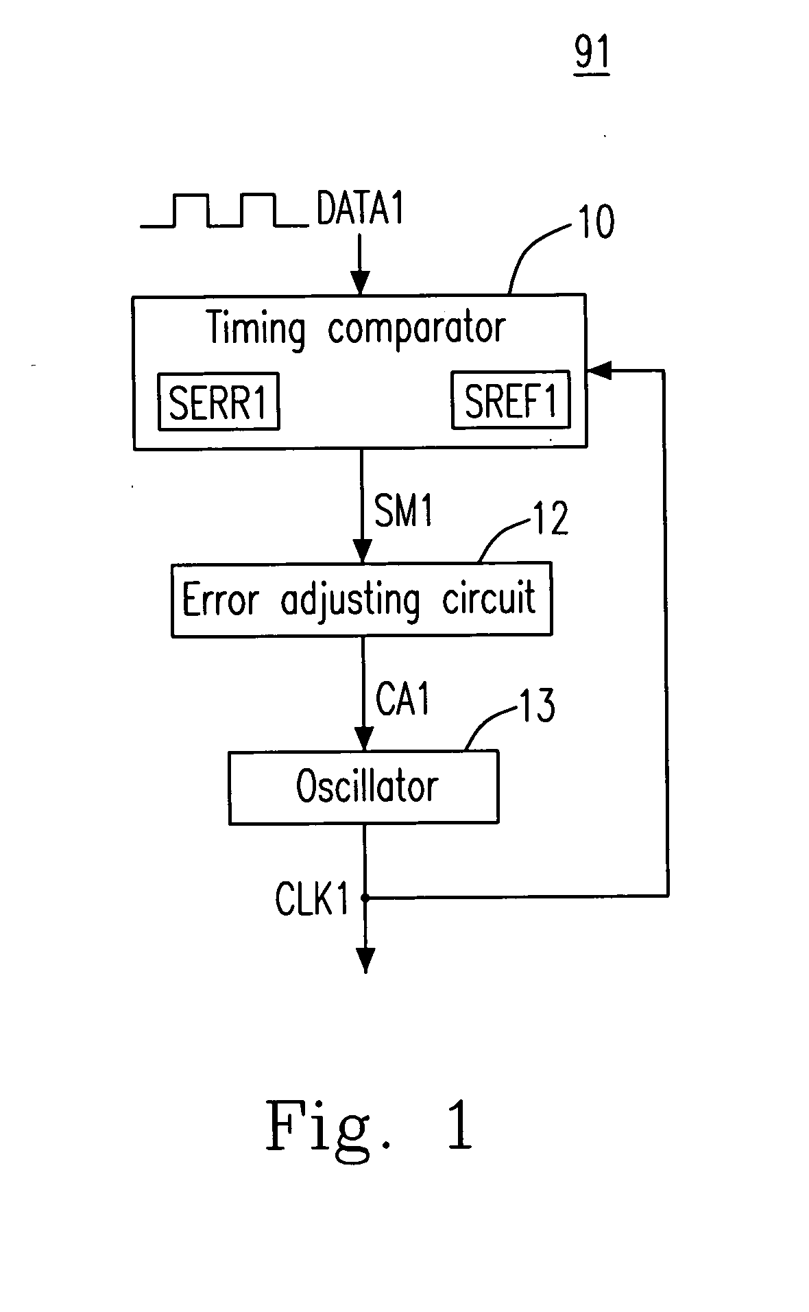
[0023]Please refer to FIG. 1, which is a schematic diagram showing an oscillation adjusting circuit according to the present invention. As shown, the oscillation adjusting circuit 91 includes an oscillator 13, a timing comparator 10, and an error adjusting circuit 12, wherein the oscillation adjusting circuit 91 may be inside a receiver (not shown) at a receiving terminal. The oscillator 13 produces an output signal CLK1 having a first period, wherein the first period is a reciprocal of a first frequency of the output signal CLK1.
[0024]The timing comparator 10 receives the output signal CLK1 and an input data stream DATA1 with a known time interval, determines an error signal SERR1 representing a difference between the known time interval and a measured duration of the known time interval, determines a reference error signal SREF1 according to a predetermined multiple of the first period, and compares the first error signal SERR1 with the reference error signal SREF1 for producing a...
second embodiment
[0027]Please refer to FIG. 3, which is a schematic diagram showing an oscillation adjusting circuit according to the present invention. As shown, the oscillation adjusting circuit 92 includes a timing comparator 20, a successive approximation register (SAR) adjusting circuit 22, an oscillator 23, and a divider 26, wherein the timing comparator 20 includes a timing processor 21, a control unit 25, and a divider 24. The control unit 25 is coupled to the timing processor 21, the SAR adjusting circuit 22, and the divider 24 and controls the operation of the timing processor 21, the SAR adjusting circuit 22, and the divider 24. There is a signal TS between the control unit 25 and the timing processor 21. There is a signal CS between the control unit 25 and the. SAR adjusting circuit 22. There is a signal DS between the control unit 25 and the divider 24.
[0028]The oscillator 23 produces an output signal OSC having a period TOSC, wherein the period TOSC is a reciprocal of a frequency fOCS ...
third embodiment
[0032]Please refer to FIG. 4, which is a schematic diagram showing an oscillation adjusting circuit according to the present invention. The oscillation adjusting circuit 93 depicts the detail of the oscillation adjusting circuit 92 in FIG. 2, wherein the repetitive descriptions are omitted. As shown in FIG. 4, the timing processor 21 includes an edge detector 211 and an error comparator 212.
[0033]The edge detector 211 is coupled to the control unit 25, is controlled by the control unit 25, receives the input data stream DATA2 and the frequency division signal OSCDIV, detects pulse edges of the input data stream DATA2 and pulse edges of the frequency division signal OSCDIV, determines a first starting and a first ending time points of the known time interval TFRAME and a second starting and a second ending time points of the measured duration TOSCDIV for producing an error signal SERR2 including an error time interval signal SPD2 and a fast-slow signal SFS2, wherein the error time in...
PUM
 Abstract
Description
Claims
Application Information