
Floor panel for a vehicle

Inactive Publication Date: 2009-09-17
FAROEX
View PDF28 Cites 34 Cited by
  • Summary
  • Abstract
  • Description
  • Claims
  • Application Information

AI Technical Summary

Benefits of technology

[0030]each of the first and second sheets being formed of a fiber reinforced material so as to provide strength against tension in both a longitudinal direction and a transverse direction;
[0051]It has been found by analysis that the main culprit is the direct, rigid link between the face skins, which is a function of the upstanding walls of the tubular cells of the honeycomb that encapsulates the polyurethane foam filling, and the resin tunnels that communicate between the face sheets. The resin tunnels facilitate transfer of resin through the core to the top and bottom layers of glass reinforcement. During the infusion process, resin is drawn through the dry reinforcement, into the tunnels, and through to the opposing face sheet, where it saturates the mat as well as the walls of the honeycomb. There is of course resin trapped in the vertical tunnels, which cures and becomes a rigid column. Together with the walls of the honeycomb, these columns transmit high frequency sound energy from the vehicle chassis to which the panel is bonded, to the interior face sheet. The face sheet is energized and the sound energy amplified.
[0054]It is known in the industry that plywood floors can be laminated with a visco-elastic veneer located at the neutral axis of the laminate. This is known as DB plywood and has been shown to effectively reduce the transmission of sound energy. Unfortunately, DB plywood is also substantially weaker than standard plywood, and subject to early failure due to delamination of the veneers under cyclical loading. The bond between the visco-elastic (usually vinyl) layer and the less flexible wood veneers results in delamination and the formation of a pocket in the plywood. Constant flexing of the veneers over the pocket results in pulverization of the veneers and eventually, the plywood “holes” through.
[0055]It is of course important in the present invention that the construction does not compromise the structural integrity of the sandwich, does not add to the light weight of the sandwich, and at the same time impedes the direct transmission of sound to the interior or tread sheet.
[0056]In a first embodiment a face sheet reinforcement is laid down as and a layer of foam-filled honeycomb core is laid over the reinforcement. The layer is equal to one third of the total core thickness to be encapsulated between the face sheets. A layer of non-woven polyester veil is laid over the first core sheet. The veil acts as an interface between the cores and becomes saturated with resin in the infusion process, binding the internal cores together. The acoustical barrier is laid over the veil. The layer is equal to one third of the total core thickness to be encapsulated between the face sheets. The acoustical barrier is comprised of high-density, closed cell foam encapsulated between two thin face sheets of aluminum foil. The acoustical barrier should not extend to the limits of the part to be molded; rather, the barrier covers roughly 60% of the total surface area and may be located in spots on the floor where there is likely to be more sound energy transmitted from the chassis. Standard honeycomb core is placed around the edges of the barrier core to fill out the core to the edges of the part. Another layer of veil is placed over the entire core surface, followed by a final layer of foam-filled honeycomb core, which extends to the extremities of the part. This layer is equal to one third of the total core thickness to be encapsulated between the face sheets. It is in turn overlaid with face sheet reinforcement. The sandwich is then resin infused. The resulting sandwich is acoustically “dead”, transmitting very little acoustic energy. The foil is a component of the molding process in that it protects the acoustic foam core from the momentarily corrosive effects of the styrene monomer contained in the laminating resin. It also serves as a barrier to thermal radiation.

Problems solved by technology

However these proposals have been put forward in a manner that does not fully address one or more of the critical market entry or performance criteria resulting in a vehicle that has limited appeal or cannot meet the rigorous performance standards dictated by the transit agencies.
Den Oudsten Bussen created the RET X-98 which was to enter revenue service in Rotterdam, but aside from stirring momentary interest at a few shows, the modular vehicle could not save the company from bankruptcy.
The license for the Fokker Stork body technology is held in North America by New Flyer but this again has achieved no commercial success.
The multiple mold strategy of course provides a huge tooling expense.
The multiple module technique has inherent weaknesses.
Up till now, therefore, no commercial vehicle of this type has been successfully exploited.

Method used


Image

  • Floor panel for a vehicle
  • Floor panel for a vehicle
  • Floor panel for a vehicle

Examples


first embodiment

[0095]In the first embodiment shown in FIGS. 5, 6 and 7, the face sheet reinforcement 75 is laid down and a first layer 92 of the foam-filled honeycomb core is laid over the reinforcement sheet. The layer 92 is approximately equal to one third of the total core thickness to be encapsulated between the face sheets 75 and 77. This proportion of the total thickness may vary particularly where the total thickness varies as in the complex panel constructions.

[0096]A layer of non-woven polyester veil 97 is laid over the first core sheet 92. The veil 97 is a conventionally available material commonly used in fiber reinforcement structures and acts as an interface between the layers 92 and 91 when it becomes saturated with resin in the infusion process, binding the internal layers together. The second layer 91 which forms an acoustical barrier is laid over the veil 97.

[0097]The layer 91 is again approximately equal to one third of the total core thickness to be encapsulated between the face...

second embodiment

[0103]In the second embodiment, the construction is very similar with three layers as previously described. In this embodiment, the layers 90 and 92 of foam-filled honeycomb core are equal to slightly less than half of the total core thickness to be encapsulated between the face sheets 75 and 77. The layers 97, 97A of non-woven polyester veil are provided as described above. The acoustical barrier 91X is laid over the veil. The layer is roughly 0.06″ (1.5 mm) thick and comprised of non-vulcanized cork which contains as little rubber as possible. The acoustical barrier 91X does not extend to the limits of the panel. A fibrous mat 91Z of required thickness roughly equal to the center layer such as Rovicore™ lofted reinforcement or UPICAMat™ core is placed around the edges of the barrier sheet to fill out the gap between the edges of the sheet and the edges of the part. Another layer of veil is placed over the entire core surface.

[0104]The third or center layers 91 are formed of a homo...


PUM

PropertyMeasurementUnit
Thicknessaaaaaaaaaa
Densityaaaaaaaaaa
Resilienceaaaaaaaaaa

Abstract

A structural shear panel for forming a floor panel for support by a vehicle frame is formed by a composite of top and bottom sheets and a core with a vacuum infused resin. The core is formed of top and bottom layers each formed from a honeycomb panel defining an array of hexagonal tubular cells with walls which extend in the thickness direction filled with a foam material. A third layer is located between the first and second layers and is formed of a material such as foam, rubber or cork which is free from tubular cells in the thickness direction and free from rigid structural members in the thickness direction to reduce communication of sound through the panel.

Description

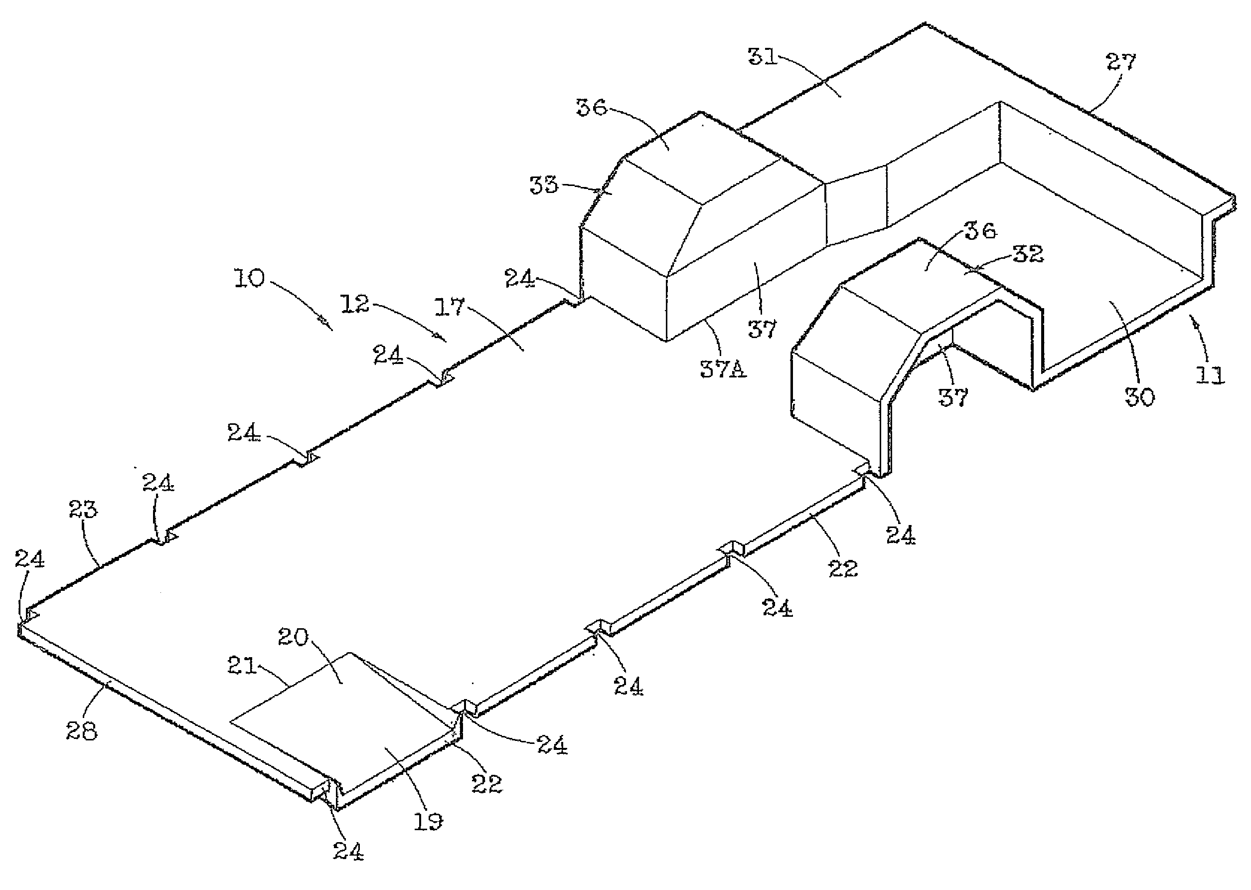
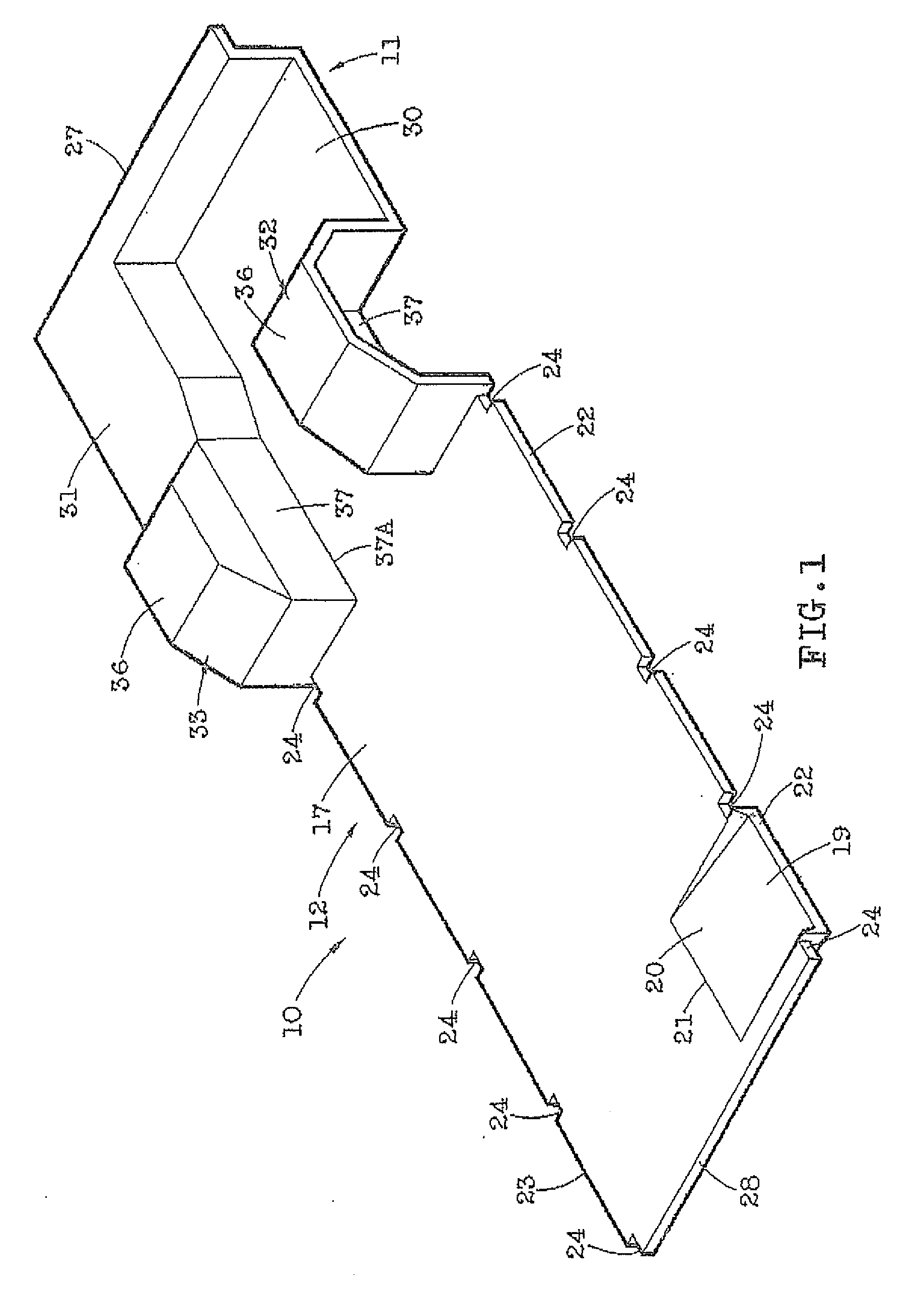
[0001]This invention relates to a floor panel to be used for example in a vehicle.BACKGROUND OF THE INVENTION[0002]There has been an intention in the industry of mass transit vehicles to provide a vehicle body which is formed primarily of a composite material. Such composite materials generally comprise fibreglass reinforced resin sheets and often these are formed with a foam or other core layer between the sheets. The primary intention is that the structure be formed substantially wholly from such composite materials. The intention is that such materials will reduce weight and provide a superior corrosion resistance. One technique is to provide molds in which the body is shaped and formed from separate pieces which can then be connected together. However one highly desirable feature is that the structure can provide multiple different vehicle lengths to satisfy customer demands.[0003]A number of attempts have been made for example, by Grumman ATTB, NABI who provided 40 and 45 feet ...

Claims


Application Information

Patent Timeline
IPC IPC(8): B62D25/20
CPCB29C70/443B62D31/02B62D29/043B62D25/2054
Inventor LUSK, KEVIN
Owner FAROEX
Learn More